 English
 Español
 Deutsch

-
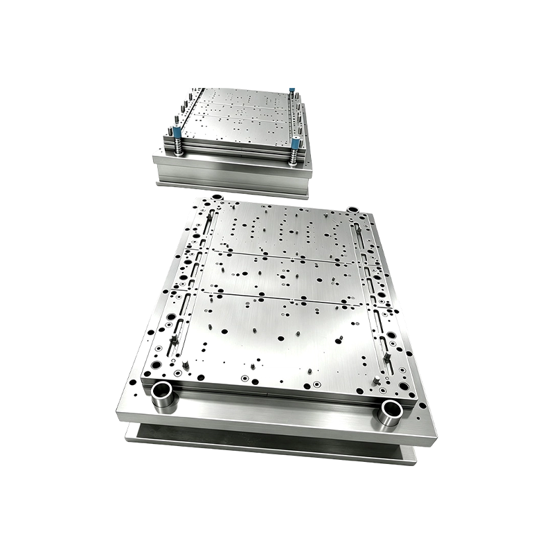
Progressive Stamping Die for Connector & Terminal Parts High Speed Progressive Stamping Die Precision Metal Hardware Stamping Tool mold for Connector Terminal Parts Automotive Components
Progressive Stamping Die for Connector & Termi...
-
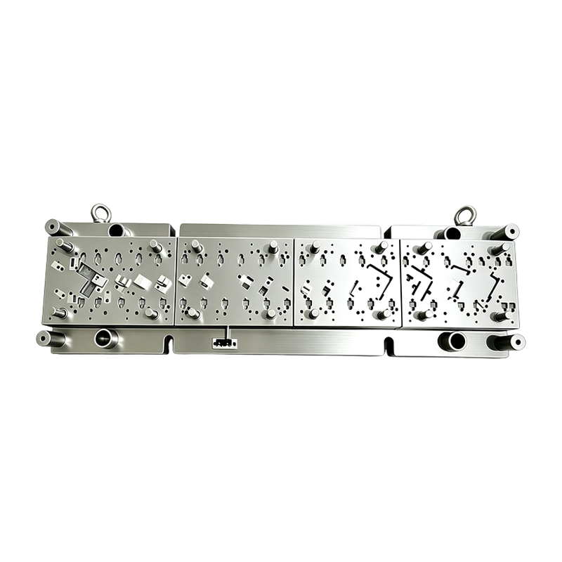
High Speed Progressive Stamping Die Sheet Metal Follow on Press Tool
Multi-operation Metal Stamping Tool for Continuous...
-
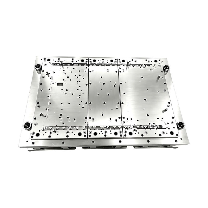
High Precision Stamping Die Multi Station Hardware Progressive Mold Tooling
Precision Metal Stamping Tool for Automotive &...
-
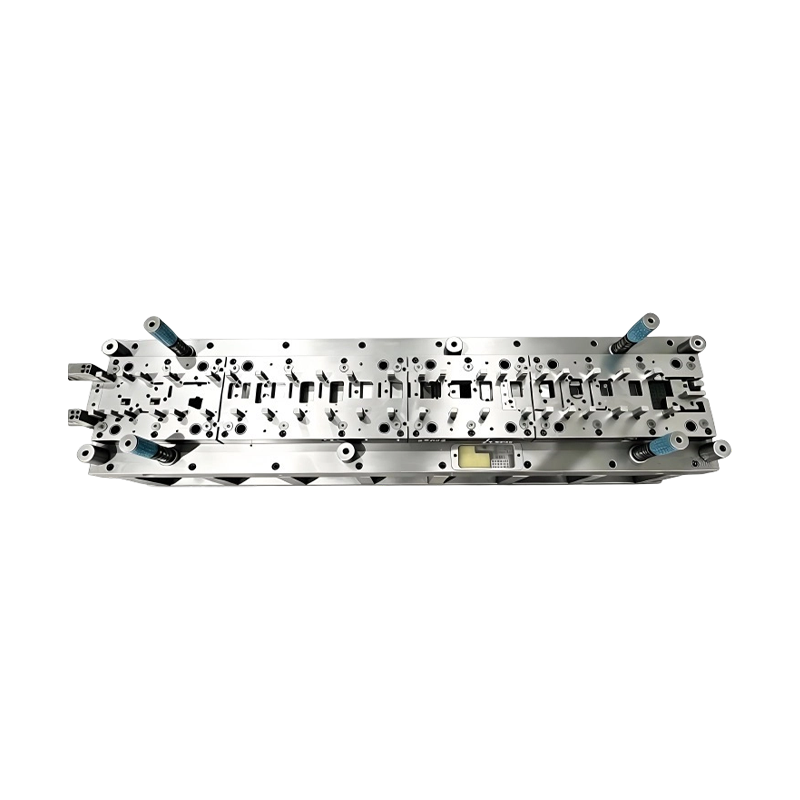
Long-Stroke Multi-Stage Progressive Die Automatic Strip Feed Progressive Die Long Travel Follow on Stamping Tool for Sheet Metal Hardware Press Moulding
Long-Stroke Multi-Stage Progressive DieOur custom ...
-
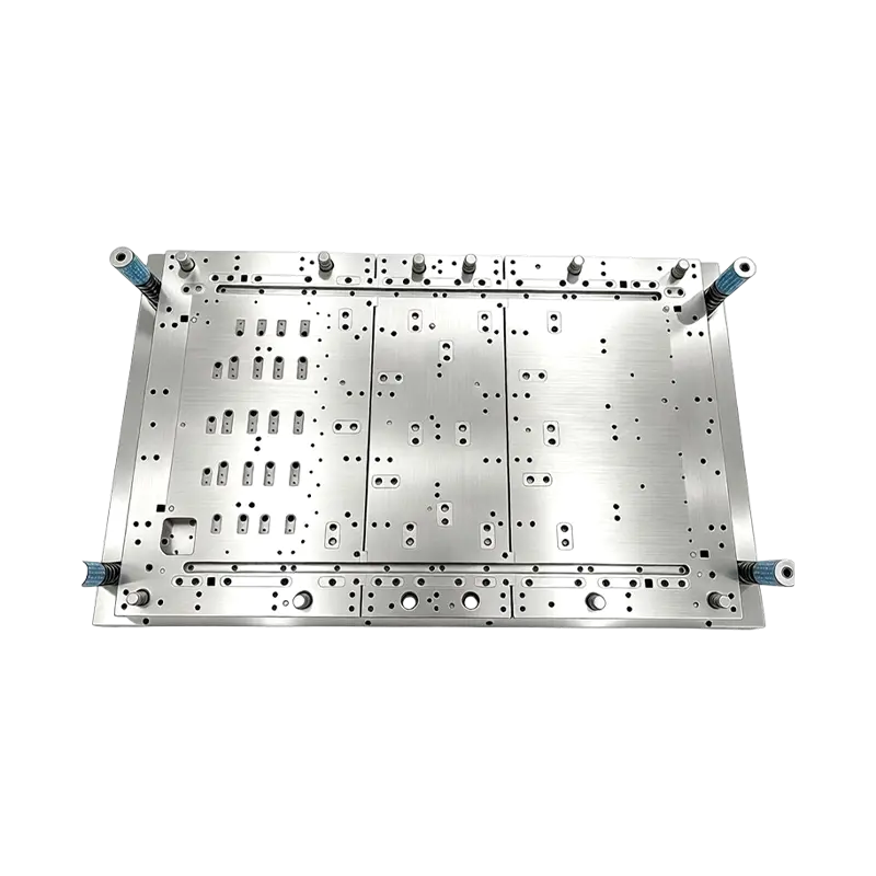
Multi-Station Progressive Stamping Die with Carbide Inserts Custom Multi Station Progressive Stamping Die Carbide Insert Metal Stamping Mold Tool for Equipment Appliances Device Hardware
High Speed Metal Stamping Tool for Precise Equipme...
-
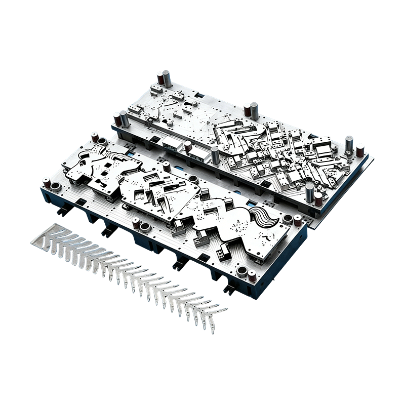
Progressive molds for automotive parts
This Continuous mold for automotive motor housing ...
- E-mail us: [email protected]
- Call us: +86-139 1308 8972

Zhou Mengjie – Technical Sales Specialist
Home / Author / Zhou Mengjie – Technical Sales Specialist / Progressive Stamping Dies for High-Speed Connector, Terminal, and Automotive Metal Parts
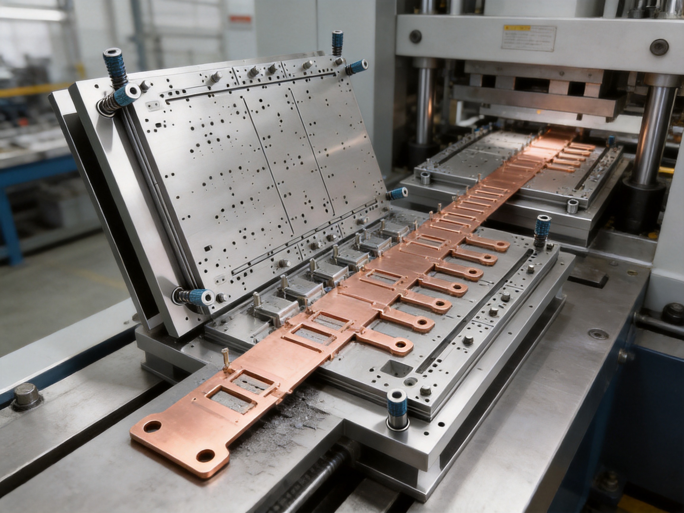
Progressive Stamping Dies for High-Speed Connector, Terminal, and Automotive Metal Parts
2026-10-20
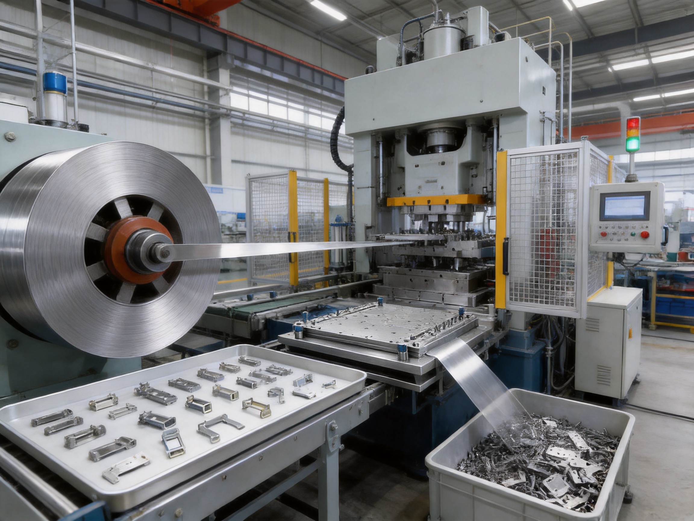
Progressive stamping is one of the most efficient manufacturing methods for producing large quantities of small, precise metal components. It combines several forming operations into one integrated die and allows a metal strip to move continuously through a press. With every press stroke, a finished or partially finished part advances from one station to the next. Piercing, notching, bending, embossing, flanging, forming, and blanking can therefore be completed in a controlled sequence without transferring individual workpieces between separate tools.
For connector terminals, electrical contacts, automotive hardware, sensor components, spring contacts, shielding parts, and other precision metal products, the quality of the progressive stamping die directly affects production efficiency, dimensional accuracy, scrap rate, and long-term manufacturing cost. A well-designed die must maintain accurate strip feeding, withstand repeated high-speed impact, control material flow, evacuate scrap effectively, and remain easy to maintain throughout a long production program.
Suzhou Shuangqisi Mold Equipment Co., Ltd. provides custom progressive stamping dies for high-volume metal component production. The company integrates die design, precision machining, assembly, tryout, sample delivery, stamping production support, and automation equipment capability. Its manufacturing resources include imported wire cutting machines, CNC machining centers, more than ten grinding machines of different sizes, and 25 punch presses with capacities ranging from 80 tons to 400 tons. Supported by approximately 60 technical employees, senior machine operators, and experienced debugging personnel, the company serves customers requiring stable tooling performance and practical production solutions.
This article explains the structure, advantages, manufacturing process, applications, and customization capability of high-speed progressive stamping dies for connector, terminal, and automotive components.
Progressive Stamping Die for Connector & Terminal Parts High Speed Progressive Stamping Die Precision Metal Hardware Stamping Tool mold for Connector Terminal Parts Automotive Components
Content
- 1 What Is a Progressive Stamping Die?
- 2 Why Progressive Dies Are Important for Connector and Terminal Parts
- 3 Key Advantages of the Custom Progressive Stamping Die
- 4 High-Precision Pilot Pin Positioning System
- 5 Carbide Inserts and Wear-Resistant Tooling
- 6 Rigid Four-Guide-Pillar Die Structure
- 7 Multi-Station Forming Capability
- 8 Scrap Evacuation and Anti-Jam Design
- 9 Manufacturing Process for the Progressive Stamping Die
- 9.1 1. Technical Review and Product Feasibility
- 9.2 2. Strip Layout Development
- 9.3 3. Die Structure and Component Design
- 9.4 4. Precision Machining
- 9.5 5. Heat Treatment and Surface Preparation
- 9.6 6. Assembly and Initial Inspection
- 9.7 7. Press Tryout and Debugging
- 9.8 8. Sample Delivery and Customer Approval
- 10 Company Manufacturing Strengths
- 11 Integrated Stamping Die and Automation Solutions
- 12 Applications of the Progressive Stamping Die
- 13 Customization Options
- 14 Advantages Compared with Conventional Multi-Tool Production
- 15 Quality and Production Control
- 16 Maintenance Recommendations
- 17 How to Select the Right Progressive Stamping Die Supplier
- 18 Project Workflow for Customers
- 19 Frequently Asked Questions
- 19.1 What parts are suitable for a progressive stamping die?
- 19.2 Can the die process thin metal strip?
- 19.3 How does the pilot pin system improve production?
- 19.4 Why are carbide inserts used?
- 19.5 Can the die operate at high stamping speeds?
- 19.6 What materials can be stamped?
- 19.7 Can the company manufacture a die from a 3D model?
- 19.8 Does the company provide samples?
- 19.9 Can the die be integrated with stamping automation?
- 19.10 How can tool life be extended?
- 19.11 What information should be included in an inquiry?
- 20 Conclusion
- 21 References
- 22 Product: Progressive Stamping Die for Connector & Terminal Parts High Speed Progressive Stamping Die Precision Metal Hardware Stamping Tool mold for Connector Terminal Parts Automotive Components
What Is a Progressive Stamping Die?
A progressive stamping die is a multi-station tool designed to perform a series of operations on a continuously fed metal strip. The strip enters the die from a coil and advances by a controlled pitch after each press stroke. At every station, a specific operation is performed. The part gradually takes shape as it moves through the die, and the final component is separated from the carrier strip at the last station.
Unlike a single-operation die, a progressive die does not require the operator or an automated transfer system to remove and reposition each individual blank between operations. The strip itself acts as the transport medium. This arrangement significantly reduces handling, shortens the production cycle, and makes the process suitable for continuous automatic stamping.
A typical progressive die for connector or terminal parts may include the following stations:
1. Strip entry and carrier preparation.
2. Pilot hole piercing for accurate positioning.
3. External profile cutting or notching.
4. Internal hole piercing.
5. Embossing or coining.
6. Bending and forming.
7. Flanging or curling.
8. Final separation and blanking.
The exact layout depends on the component geometry, material grade, thickness, tolerance, production volume, and required press speed. Complex connector and automotive parts may require many closely coordinated stations. The die designer must calculate the forming sequence, cutting clearance, strip utilization, carrier strength, press tonnage, springback compensation, and scrap evacuation method before machining begins.
Why Progressive Dies Are Important for Connector and Terminal Parts
Connector and terminal components are often small, thin, and geometrically complex. A single part may contain multiple holes, narrow slots, locking features, contact beams, embossed areas, retention hooks, or precisely angled bends. These details must be produced consistently because even a small dimensional error can affect electrical contact resistance, insertion force, retention strength, assembly alignment, or product reliability.
Progressive stamping is especially suitable for these parts because it offers repeatable production at high speed. The strip remains supported by a carrier during most of the process, which helps control the location of delicate features. Each station performs a limited operation, allowing the tooling to distribute forming loads and reduce the risk of excessive deformation.
High-volume connector production also demands consistent pitch accuracy. If the strip advances unevenly, errors accumulate along the strip and may cause holes, bends, or contact features to shift from their intended locations. A high-precision pilot pin positioning system helps correct and control strip position before critical operations are performed.
The combination of accurate piloting, rigid die construction, carbide cutting components, optimized station design, and reliable scrap discharge gives progressive stamping dies a major advantage over less integrated tooling approaches. Production can continue with fewer interruptions, lower labor requirements, and a more predictable cost per part.
Key Advantages of the Custom Progressive Stamping Die
High-Speed Continuous Production
The die is designed for continuous coil feeding and automatic press operation. Once the coil, feeder, press, and die are correctly set up, the production line can manufacture parts with minimal manual intervention. This is particularly valuable for terminals, clips, contacts, brackets, and other products required in large quantities.
High-speed operation reduces the time required to manufacture each part and improves the utilization of the press. Compared with multiple standalone dies, an integrated progressive die reduces the need for repeated loading, unloading, repositioning, and intermediate inspection. It also minimizes the floor space and equipment required for a complete production process.
Consistent Dimensional Accuracy
Every station is designed according to the same strip layout and reference system. This enables the relationship between holes, edges, bends, and formed features to remain stable throughout the production run. Properly controlled die clearances and precision-machined inserts support consistent cutting quality and help reduce burrs.
For parts used in electrical and automotive assemblies, consistency is often more important than the nominal dimension of a single feature. The position of a contact beam relative to a locking tab, the distance between two mounting holes, or the angle of a terminal bend may determine whether the component performs correctly. Progressive tooling enables these relationships to be controlled within one coordinated tool.
Reduced Production Labor
Because the strip moves automatically through the die, fewer operators are needed for material handling. The production team can focus on coil loading, press setup, quality inspection, tool maintenance, and packaging rather than manually transferring parts between forming stages.
Lower labor requirements can be especially beneficial in high-volume programs. The resulting process is more repeatable, less dependent on operator handling, and easier to integrate into an automated stamping cell.
Lower Fixture and Equipment Costs
When a component is manufactured with several separate dies, each stage may require its own fixture, feeding system, intermediate container, and inspection arrangement. A progressive die combines the necessary stations into one tool, reducing the number of separate production resources.
This does not mean that progressive tooling is appropriate for every product. For low-volume or very large components, other processes may be more economical. However, for small to medium-sized parts with stable demand and multiple operations, progressive stamping can provide a strong balance between tooling investment and long-term production cost.
Long Tool Life
Critical cutting and forming areas use tungsten carbide inserts where appropriate. Carbide offers high hardness and excellent wear resistance, making it suitable for sections exposed to repeated cutting, sliding, and impact. Professional surface treatment or coating can further reduce friction, material pickup, galling, and premature wear.
With correct material selection, heat treatment, clearance design, lubrication, maintenance, and press setup, the die can support a long production program. The supplied product information indicates that the tool can be engineered for service life reaching tens of millions of shots, depending on material, part geometry, operating conditions, maintenance, and production parameters.
Stable High-Speed Running
High-speed stamping places severe demands on die alignment and structural rigidity. The die must remain parallel under repeated impact, and the moving components must return accurately after every stroke. A rigid die base and four-guide-pillar structure help maintain alignment between the upper and lower sections.
Stable running also depends on balanced station loading. The die design team must distribute cutting and forming forces carefully so that the press does not experience excessive unbalanced loads. Properly arranged force distribution helps reduce vibration, noise, premature guide wear, and part deformation.
Convenient Maintenance
The modular insert structure allows selected cutting or forming components to be removed and replaced without rebuilding the complete die. This simplifies repair and can reduce downtime when a high-wear component requires service.
Modularity is also useful during product development. If a customer changes a hole, bend, notch, or local forming feature, the affected insert may be modified more efficiently than a fully integrated die block. The final maintenance strategy depends on the die layout, but a modular approach generally improves accessibility and serviceability.
High-Precision Pilot Pin Positioning System
Accurate strip positioning is one of the most important factors in progressive stamping. The feeder establishes the approximate pitch, while pilot pins provide precise location before critical operations. The pilot pins enter previously pierced pilot holes and correct small feeding deviations so that the strip is aligned with the next station.
The die uses high-hardness pilot pins designed for repeated engagement with the strip. Their purpose is to control cumulative pitch error and maintain consistent registration during continuous production. This is especially important when the strip contains narrow terminal profiles, closely spaced holes, or multiple stations with tight positional relationships.
Without reliable piloting, several problems may occur:
• Hole positions may drift from station to station.
• Bends may be formed at the wrong location.
• Contact beams may become asymmetrical.
• The carrier may be damaged or pulled out of alignment.
• The finished part may fail assembly or electrical performance requirements.
• Scrap may increase during high-speed operation.
The pilot system is designed together with the strip layout, feeder pitch, carrier width, and station sequence. It is not an isolated component. The timing of pilot engagement, pilot release, stripper movement, and press travel must be coordinated to prevent interference or strip distortion.
Carbide Inserts and Wear-Resistant Tooling
Cutting edges in a progressive stamping die experience repeated contact with the material. Over time, wear can change the cutting clearance, increase burr height, affect hole size, and alter the outside profile of the part. Forming areas may also suffer from galling or material buildup, particularly when processing stainless steel, copper alloys, spring materials, or other difficult-to-form metals.
Tungsten carbide inserts are used in critical areas to improve wear resistance and preserve cutting performance. These inserts may be applied to piercing punches, cutting edges, blanking sections, or selected forming components according to the stress and wear conditions of each station.
Surface coating can provide an additional layer of protection. The appropriate coating depends on the material being stamped, the required speed, lubrication, forming pressure, and expected tool life. A correctly selected coating can reduce friction, improve resistance to adhesive wear, and reduce the tendency of the work material to stick to the tool surface.
Carbide and coating selection must be supported by correct tool geometry. A high-performance material cannot compensate for poor clearance, insufficient support, incorrect edge preparation, or improper alignment. For this reason, the company combines material selection with precision machining, grinding, assembly, and tryout to confirm the performance of the complete tool.
Rigid Four-Guide-Pillar Die Structure
A progressive die must maintain accurate alignment during high-frequency reciprocating motion. The guide system ensures that the upper die set travels along a controlled path relative to the lower die set. The four-guide-pillar structure provides stable support and helps maintain parallelism across the working area.
Rigid construction is particularly important when a tool contains many stations. Each station must remain aligned with its corresponding punch, die insert, stripper, lifter, and forming component. Even a small amount of angular or lateral movement can lead to premature wear, punch breakage, inconsistent burrs, or dimensional variation.
The die base, guide components, backing plates, stripper system, and insert supports are selected and arranged according to the load requirements of the application. Proper support beneath cutting inserts reduces deflection, while accurate guide clearance supports smooth movement. The objective is to create a tool that remains stable not only during initial tryout but also after extended production.
Multi-Station Forming Capability
The progressive die can integrate numerous operations within one production tool. Depending on the customer’s part design, these may include piercing, notching, bending, embossing, flanging, coining, forming, and final blanking.
Piercing and Notching
Piercing creates internal holes, slots, and openings. Notching removes material from the edge of the strip or part profile. These operations require carefully controlled punch-to-die clearance. Excessive clearance may produce large burrs and poor edge quality, while insufficient clearance may increase press load and accelerate punch damage.
Bending and Forming
Bending stations create the angles, hooks, tabs, and contact shapes required by the finished part. The design must account for material thickness, yield strength, rolling direction, springback, bend radius, and the sequence of adjacent forming operations.
Progressive forming is often performed in stages rather than one severe bend. Gradual forming reduces stress concentration and helps preserve the shape of narrow or delicate features. The die may use forming punches, inserts, lifters, pressure pads, and restraining surfaces to control the material during each step.
Embossing and Coining
Embossed features can improve stiffness, provide locating points, create electrical contact surfaces, or add a designed profile to a terminal or bracket. Coining may be used to refine a local area, flatten a surface, or improve dimensional definition. These operations must be carefully balanced against the risk of work hardening, cracking, or distortion.
Final Blanking and Part Separation
The final station separates the finished component from the carrier strip. The separation method depends on the part geometry, edge requirements, downstream handling system, and whether the customer requires loose parts, linked components, or a controlled carrier format.
Correct final blanking is essential. If the part is not fully supported during separation, it may twist, deform, or remain attached to the scrap web. The die layout therefore considers the final carrier connection, scrap direction, part discharge, and interaction with any automation equipment.
Scrap Evacuation and Anti-Jam Design
Scrap management is a major factor in reliable high-speed stamping. Small offcuts, slugs, skeleton sections, and trimmed carrier material must leave the die without interfering with the next stroke. A trapped scrap fragment can damage a punch, lift the strip, block a station, or cause a serious die crash.
The die incorporates optimized scrap evacuation and anti-jam measures to reduce these risks. Openings, chutes, discharge paths, air assistance, slug retention features, and carrier design may be used according to the material and part layout. The objective is to guide scrap away from active areas and prevent loose pieces from jumping back into the tool.
Strip warping is another concern. Thin materials can curl or twist after repeated cutting and forming. The die must provide adequate support and control the sequence of material removal so that the remaining carrier maintains enough strength until the required stations are completed.
Effective scrap management improves more than machine reliability. It also reduces unplanned downtime, protects expensive inserts, improves workplace safety, and supports a cleaner production environment.
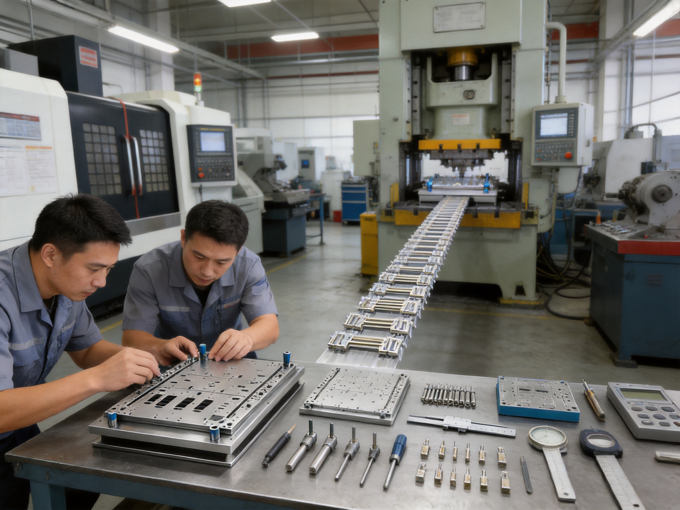
Manufacturing Process for the Progressive Stamping Die
1. Technical Review and Product Feasibility
The process begins with a review of the customer’s 2D drawings, 3D models, material specification, thickness, tolerance requirements, expected annual volume, press conditions, and production speed. The engineering team studies the part geometry and identifies potential risks such as narrow sections, difficult bends, insufficient carrier width, excessive forming loads, or features that may interfere with adjacent stations.
At this stage, the team may recommend changes to corner radii, hole placement, bend sequencing, carrier connections, or material flow. Early design-for-manufacturing analysis can prevent expensive changes after die machining begins.
2. Strip Layout Development
The strip layout defines how the raw material will move through the die. Engineers determine the feeding direction, station pitch, carrier arrangement, material utilization, pilot hole positions, scrap bridges, and operation sequence.
A good layout balances several objectives. It must achieve reliable forming and cutting while minimizing material waste. It must also preserve enough carrier strength for high-speed feeding. The layout affects press tonnage, die width, tool complexity, part quality, and operating cost.
3. Die Structure and Component Design
After the strip layout is established, the complete die structure is developed. This includes the die base, guide pillars, punches, die inserts, stripper plates, pressure pads, lifters, forming blocks, pilot pins, springs, fasteners, and scrap discharge features.
The design team considers how each component will be assembled, adjusted, inspected, lubricated, and replaced. Modular construction is used where practical to support future maintenance and reduce downtime.
4. Precision Machining
Machining is performed using CNC equipment, imported wire cutting machines, grinding machines, and other precision tools. Wire cutting is suitable for producing complex profiles and fine cutting sections with high accuracy. CNC machining centers are used for die plates, bases, pockets, support surfaces, and three-dimensional components.
Grinding is important for achieving accurate dimensions, flatness, parallelism, and surface finish. The company operates more than ten grinding machines of different sizes, allowing various die components to be processed according to their dimensions and accuracy requirements.
5. Heat Treatment and Surface Preparation
Selected tool components receive appropriate heat treatment to achieve the required hardness and toughness. The treatment must be controlled carefully because excessive hardness may make a component brittle, while insufficient hardness can shorten service life.
After heat treatment, components may require finish grinding or additional processing to restore dimensional accuracy. Surface preparation and coating decisions are made according to the material and operating conditions of the die.
6. Assembly and Initial Inspection
Precision components are assembled into the die set and checked for fit, movement, clearance, alignment, and interference. Pilot pins, punches, inserts, strippers, springs, and forming components must operate smoothly before the die is installed in a press.
Inspection may include dimensional measurement, flatness checks, parallelism verification, profile inspection, and functional checks of moving sections. The purpose is to identify assembly issues before tryout and reduce the time required for press adjustment.
7. Press Tryout and Debugging
Tryout verifies whether the die performs correctly under actual stamping conditions. The tool is installed in a suitable press, and material with the specified grade and thickness is fed through the die. Engineers and debugging personnel evaluate strip feeding, pilot engagement, cutting quality, forming accuracy, press load, scrap evacuation, and finished part dimensions.
Adjustments may include cutting clearance, forming height, stripper pressure, spring force, feeder timing, pilot timing, insert position, or local relief. Several tryout cycles may be required for complex components. The goal is not simply to produce one acceptable sample, but to establish a stable process window for continuous production.
8. Sample Delivery and Customer Approval
After tryout, sample parts are measured and prepared for customer evaluation. Dimensional reports, material information, inspection records, and relevant process notes may be supplied according to the customer’s requirements.
Customer approval confirms that the part meets its functional and dimensional expectations. If changes are requested, the design and tooling team can review the affected features and implement appropriate modifications before final delivery.
Company Manufacturing Strengths
Suzhou Shuangqisi Mold Equipment Co., Ltd. is located in the Wujiang Economic Development Zone of Suzhou, China. The company focuses on stamping dies, stamped hardware parts, and stamping automation equipment. Its integrated capabilities allow customers to obtain more than a standalone tool.
The company has approximately 15 years of experience in the mold industry and employs around 60 technical staff. Its equipment resources include imported wire cutting machines, CNC machining centers, more than ten grinding machines of various sizes, 25 punch presses from 80 tons to 400 tons, and other precision manufacturing equipment.
This combination of engineering personnel and production equipment supports the full tooling cycle, including design, machining, assembly, testing, debugging, sample production, and technical support. Customers can discuss the complete production requirement with one technical partner instead of coordinating separate suppliers for die design, die manufacturing, tryout, and automation.
The company serves customers in industries including servo drives, compressors, electrical products, and new energy vehicles. Its stated customer base includes Anter Group, Ousheng Electric, Dongbei Group, and Huichuan Technology. These applications require practical experience with repeatable stamping, precision hardware, and production efficiency.
In 2016, the company invested in and established Suzhou Keshuang Intelligent Technology Co., Ltd., which focuses mainly on stamping automation equipment. This provides an additional foundation for customers seeking automated coil feeding, transfer, collection, inspection, or related production solutions.
Integrated Stamping Die and Automation Solutions
A progressive die reaches its full value when it operates as part of a coordinated production line. The press, decoiler, straightener, feeder, die, sensor system, scrap collection, part discharge, inspection, and packaging process must work together.
Through its stamping automation capability, the company can support turnkey solutions that combine mold manufacturing with automated production equipment. Depending on the application, automation may include coil loading, straightening, precision feeding, automatic part collection, scrap separation, counting, transfer, or inspection.
Automation reduces manual handling and helps maintain a consistent operating rhythm. It can also improve safety by keeping operators away from the press point of operation. For high-volume connector and terminal production, automated handling supports stable output and reduces variation caused by manual intervention.
The company can also invest in related production equipment according to customer needs. This approach may be useful for customers that want a complete manufacturing solution rather than a die alone. The final equipment arrangement depends on part size, material, press type, cycle speed, inspection requirements, and packaging method.
Applications of the Progressive Stamping Die
Electronic Connectors and Terminals
Connector terminals require precise profiles, stable contact areas, accurately positioned locking features, and controlled bends. Progressive stamping is suitable for copper, brass, phosphor bronze, stainless steel, and other conductive or spring materials used in electronic assemblies.
Spring Contacts and Electrical Clips
Spring contacts often require multiple bends and carefully controlled contact pressure. A progressive die can gradually form the spring profile while maintaining the relationship between the contact surface and retention features.
Automotive Electrical Hardware
Automotive electrical systems use numerous small metal components in connectors, sensors, control modules, battery systems, and wiring assemblies. These parts may need high consistency because they operate under vibration, temperature variation, and repeated assembly conditions.
New Energy Vehicle Components
Electric vehicles and hybrid vehicles contain extensive electrical and battery-related hardware. Stamped conductive parts, shielding components, terminals, clips, and mounting hardware can be produced using progressive tooling when the geometry and material are suitable.
Sensor Metal Components
Sensor hardware may include brackets, contact elements, shielding pieces, retaining clips, and precision support parts. These components benefit from the repeatability and integrated forming sequence provided by a progressive die.
Consumer Electronics Parts
Internal shielding sheets, shrapnel, clips, contact springs, and small structural metal pieces are often manufactured in high quantities. Progressive stamping can produce these components with short cycle times and controlled feature placement.
Power Sockets, Relays, and Battery Hardware
Electrical products such as power sockets, relays, and battery assemblies require conductive or structural stamped pieces. The die can be customized for the required material, thickness, contact geometry, and assembly function.
| Application | Typical Features | Progressive Die Benefits |
|---|---|---|
| Electronic connectors | Slots, contact beams, locking tabs, narrow profiles | Accurate piloting, high-speed production, consistent geometry |
| Automotive terminals | Multiple bends, retention features, conductive surfaces | Integrated forming, repeatable angles, automated coil feeding |
| Sensor components | Mounting holes, brackets, shielding sections | Stable dimensional relationships and low handling requirements |
| Battery hardware | Conductive tabs, clips, terminals, formed supports | High-volume output and customizable material compatibility |
| Consumer electronics parts | Shields, springs, shrapnel, small clips | Short cycle time, reduced labor, modular maintenance |
| Relay and socket parts | Contact sections, terminals, formed electrical hardware | Multi-station piercing, bending, embossing, and blanking |
Customization Options
Every progressive stamping die is designed around a specific part and production requirement. Customers can provide 2D drawings, 3D models, samples, material details, or a combination of these resources. The engineering team then develops a tooling solution based on the actual production objectives.
Important customization parameters include:
• Part length, width, height, and profile.
• Material grade and mechanical properties.
• Material thickness and strip width.
• Required tolerances and inspection standards.
• Annual production volume.
• Target press speed or strokes per minute.
• Preferred press capacity and working area.
• Coil direction and feeding arrangement.
• Required surface finish and burr limits.
• Final part discharge and packaging method.
• Expected tool life and maintenance plan.
• Need for automation, inspection, or counting.
The die may be designed for a particular customer press or for compatibility with an available range of presses. Press tonnage, shut height, slide dimensions, bolster size, stroke length, and feeder capability must all be considered during engineering.
Advantages Compared with Conventional Multi-Tool Production
Using separate dies for piercing, bending, forming, and blanking may be appropriate for certain low-volume or simple products, but it introduces additional handling and process stages. Each transfer between operations creates an opportunity for positioning error, surface damage, and production delay.
A progressive die keeps the part in a controlled strip until the final separation stage. This improves positional consistency between features and reduces the need for intermediate storage. The integrated layout also makes it easier to connect the process with a continuous coil-feeding line.
Compared with manually operated standalone tooling, a high-speed progressive die can deliver significantly higher output with fewer operators. Compared with poorly integrated low-cost tooling, a precision die with carbide inserts, robust guiding, modular construction, and optimized scrap discharge may provide better long-term stability and lower maintenance risk.
The most important competitive advantage is not simply the number of stations. It is the relationship between engineering quality, precision machining, material selection, tryout discipline, and production support. A die that runs quickly for a short period but generates excessive burrs, frequent jams, or difficult maintenance may cost more over its life than a more carefully engineered tool.
Quality and Production Control
Quality control begins before machining. Design reviews identify potential forming problems, tolerance conflicts, and strip layout risks. Machining inspections verify critical dimensions and the condition of cutting and forming surfaces. Assembly inspections confirm that components move correctly and align as intended.
During tryout, sample parts are evaluated for dimensions, burrs, deformation, bend angles, surface condition, and overall function. The process team may also observe press load, vibration, feeding stability, scrap discharge, and tool noise. These observations help identify issues that may not be visible from a single sample part.
Production control continues after delivery. Customers benefit from clear maintenance procedures, appropriate lubrication, inspection of wear components, and prompt technical communication when operating conditions change. The company provides after-sales technical support to help customers maintain stable production and solve tooling-related problems.
For high-volume stamping, preventive maintenance is essential. Pilot pins, punches, die inserts, springs, guide components, and forming surfaces should be inspected according to production quantity and material conditions. Replacing a small wear component at the correct time can prevent damage to a larger section of the die and avoid an extended production interruption.
Maintenance Recommendations
Daily Checks
Operators should inspect the die for loose components, unusual noise, abnormal vibration, scrap accumulation, lubrication problems, and visible damage. The strip path should be kept clear, and the feeder should be checked for stable pitch and correct alignment.
Routine Cleaning
Scrap, dust, lubricant residue, and material particles should be removed from the die according to the production schedule. Clean working surfaces help prevent scratches, inaccurate seating, and interference with moving components.
Wear Inspection
Cutting edges, pilot pins, punches, die inserts, guide components, and forming surfaces should be inspected for wear, chipping, galling, or material buildup. Burr height and finished part dimensions can provide early indications of tool wear.
Lubrication and Adjustment
Lubrication must be compatible with the stamped material and the production environment. Springs, guide components, moving lifters, and selected forming surfaces may require controlled lubrication. Adjustments should be performed by trained personnel to avoid changing the intended die relationship.
Record Keeping
Maintaining records of stroke counts, repairs, insert replacements, dimensional results, and production issues helps establish a practical maintenance interval. These records also support future tooling improvements and spare-parts planning.
How to Select the Right Progressive Stamping Die Supplier
A suitable supplier should be evaluated not only by quoted tooling price but also by engineering ability, machining resources, tryout capacity, communication, and after-sales support. Customers should ask whether the supplier can review the part for manufacturability, verify the press requirements, and provide a complete strip layout before production begins.
It is also important to understand how the supplier manages critical components. Questions may include whether carbide inserts are used where appropriate, how guide alignment is checked, how pilot systems are designed, how scrap evacuation is tested, and whether modular replacement parts are available.
Manufacturing equipment is another important consideration. Access to CNC machining, wire cutting, precision grinding, appropriate presses, and experienced assembly personnel gives the supplier greater control over the tooling process. In-house tryout capability can shorten feedback cycles and reduce the risk of delivering a die that has not been adequately tested.
For customers seeking a complete production line, the supplier’s automation experience may also be decisive. A company capable of supporting the die, press process, feeding system, and related automation can help reduce coordination problems between multiple vendors.
Project Workflow for Customers
The recommended project workflow begins with the customer submitting product drawings, material details, quantity requirements, and available press information. The supplier reviews the technical data and identifies any concerns that may affect tooling cost, production speed, or part quality.
After technical clarification, the supplier develops the tooling concept, strip layout, station sequence, and preliminary production plan. The customer reviews the proposed approach before detailed design and machining commence.
The die is then manufactured, assembled, and tested. Samples are produced for dimensional and functional evaluation. Any required corrections are completed before final approval and shipment.
For customers requiring production support, the supplier can assist with press installation, die adjustment, automatic feeding, process optimization, and maintenance guidance. This makes the project more than a one-time tooling purchase; it becomes a coordinated manufacturing program.
Frequently Asked Questions
What parts are suitable for a progressive stamping die?
Progressive stamping is suitable for high-volume metal parts that require several sequential operations, such as piercing, notching, bending, embossing, flanging, and blanking. Common examples include connector terminals, electrical contacts, automotive clips, sensor hardware, battery components, shielding pieces, and small precision brackets.
Can the die process thin metal strip?
Yes. Progressive dies are widely used for thin metal strip, particularly for electronic terminals, spring contacts, and small electrical hardware. The specific material thickness, strip width, grade, and forming requirements must be reviewed during the design stage.
How does the pilot pin system improve production?
Pilot pins enter accurately positioned pilot holes in the strip and correct small feeding deviations before critical operations. This helps control cumulative pitch error and improves the positional relationship between holes, bends, embossments, and final profiles.
Why are carbide inserts used?
Carbide inserts offer high hardness and wear resistance in areas exposed to repeated cutting or forming. They can help maintain edge quality, reduce burr growth, resist material pickup, and extend the service life of critical die sections.
Can the die operate at high stamping speeds?
The die is designed for high-speed continuous stamping when the part geometry, material, press, feeder, lubrication, and process conditions are suitable. Stable high-speed operation depends on accurate guiding, balanced station loads, correct pilot timing, effective scrap discharge, and proper maintenance.
What materials can be stamped?
The suitable material depends on the part design and forming requirements. Common possibilities include copper alloys, brass, phosphor bronze, stainless steel, carbon steel, spring materials, and other thin metal strip. The material grade and thickness should be provided before die design begins.
Can the company manufacture a die from a 3D model?
Yes. The company can design and manufacture dies according to customer 2D drawings, 3D models, material specifications, tolerance requirements, and production targets. A sample or preliminary concept may also be reviewed when formal drawings are not yet complete.
Does the company provide samples?
Yes. After assembly and press tryout, sample parts can be produced for customer inspection and approval. The tryout process may include adjustments to forming height, clearance, feeding, pilot timing, and other tooling parameters.
Can the die be integrated with stamping automation?
Yes. Through its stamping automation capability, the company can support automated coil feeding and other related production equipment. The specific solution depends on the press, material, part geometry, production speed, collection method, and inspection requirements.
How can tool life be extended?
Tool life depends on correct die design, suitable tool materials, heat treatment, surface treatment, press alignment, lubrication, strip quality, and maintenance. Regular inspection of pilot pins, punches, inserts, guides, and forming surfaces helps identify wear before it causes major damage.
What information should be included in an inquiry?
Customers should provide part drawings or models, material grade, thickness, required tolerance, annual quantity, target stamping speed, available press details, surface requirements, and any special inspection or packaging needs. More complete information allows the supplier to prepare a more accurate technical proposal.
Conclusion
A high-speed progressive stamping die is a production system in tool form. Its success depends on the coordination of strip layout, pilot positioning, cutting clearance, forming sequence, die rigidity, wear resistance, scrap evacuation, press compatibility, and maintenance planning.
For connector, terminal, automotive, electrical, and new energy vehicle components, the custom progressive stamping die described in this article provides an integrated method for manufacturing complex thin metal parts at high volume. Its key advantages include continuous coil feeding, multi-station processing, accurate pilot pin positioning, carbide inserts, four-guide-pillar rigidity, modular maintenance, optimized scrap handling, and compatibility with automated stamping lines.
Suzhou Shuangqisi Mold Equipment Co., Ltd. combines die design, precision machining, grinding, assembly, press tryout, sample production, and technical support. Its equipment base, technical workforce, press capacity, industry experience, and connection with stamping automation resources enable it to provide both individual progressive dies and broader turnkey production solutions.
Customers requiring a custom tool can submit product drawings, material specifications, thickness, tolerance requirements, production volume, and press information for technical evaluation. The final die can then be engineered around the actual component and manufacturing objective, with the goal of achieving stable mass production, controlled quality, long service life, and a competitive total cost of ownership.
References
1. Society of Manufacturing Engineers, Fundamentals of Sheet Metal Stamping and Die Design.
2. American Society for Metals, ASM Handbook: Forming and Forging.
3. Metal Forming Technology, Principles of Progressive Die Design and Strip Layout.
4. Tool and Manufacturing Engineers Association, Recommended Practices for Press Tooling and Die Maintenance.
5. Internal technical information supplied for the custom progressive stamping die product and manufacturing capabilities of Suzhou Shuangqisi Mold Equipment Co., Ltd.
Product: Progressive Stamping Die for Connector & Terminal Parts High Speed Progressive Stamping Die Precision Metal Hardware Stamping Tool mold for Connector Terminal Parts Automotive Components
Previous Post
Heavy Truck Stamping Parts: Precision Components for Reliable Commercial Vehicles
Next Post
Long-Stroke Multi-Stage Progressive Dies for Complex Sheet Metal Forming
Our Products.
Start Your Business with an OEM Manufacturer Right Here!

Provide global customers with complete turn-key solutions
through
innovation!
QUICK LINKS
CONTACT INFO.
-
 +86-139 1308 8972
-

-
 No. 118 Yexin Road, Wujiang Economic Development Zone, Suzhou, China
Copyright © Suzhou Shuangqisi Mold Equipment Co., Ltd. All Rights Reserved. Custom Stamping Die Metal Stamping Die Manufacturers
