 English
 Español
 Deutsch
-
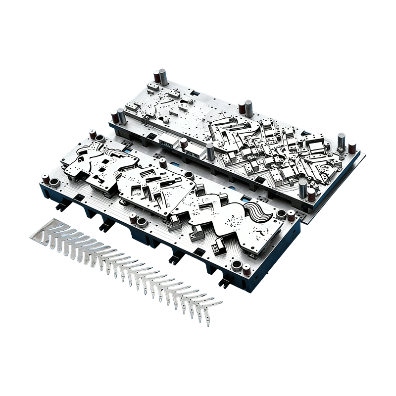
Progressive molds for automotive parts
This Continuous mold for automotive motor housing ...
-
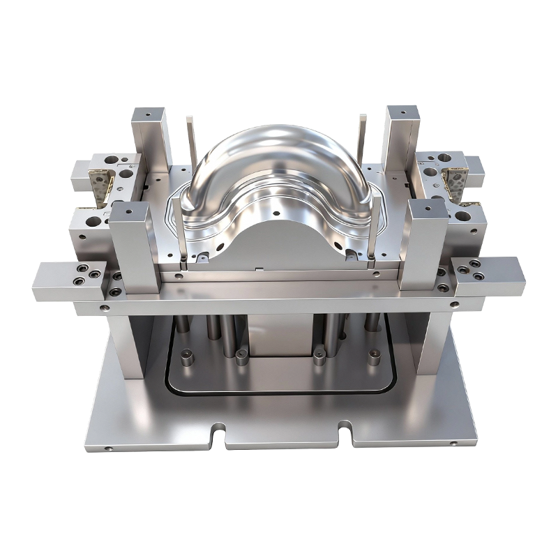
Deep drawing mold for front and rear wheels of two-wheeled electric vehicles
This Deep drawing mold for front and rear wheels o...
-
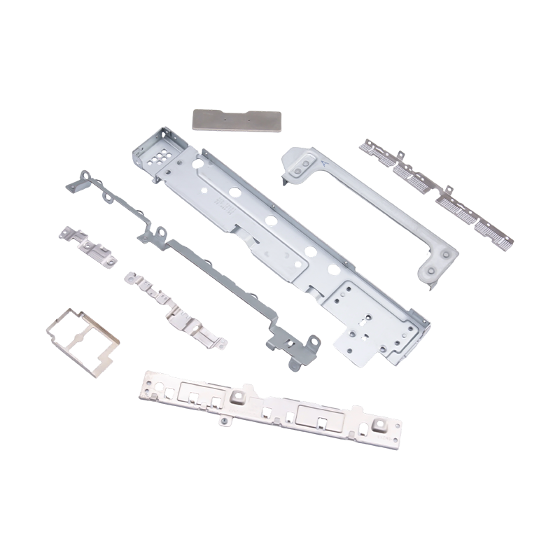
Small stamped parts for laptops and mobile phones
As essential internal components for modern portab...
-
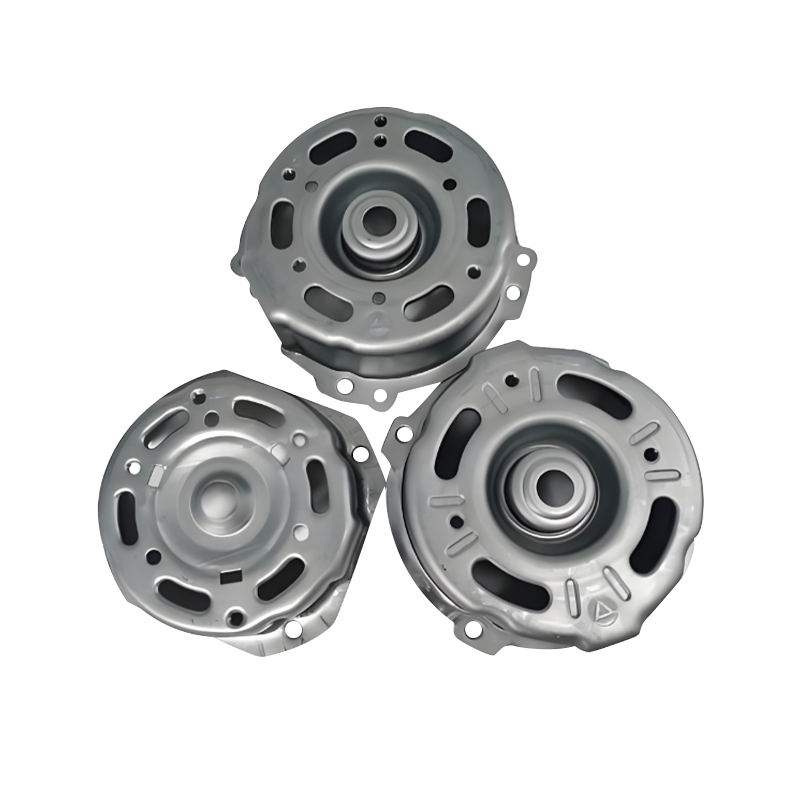
Automotive motor housing stamping parts
Automotive motor housing stamping parts are core c...
-
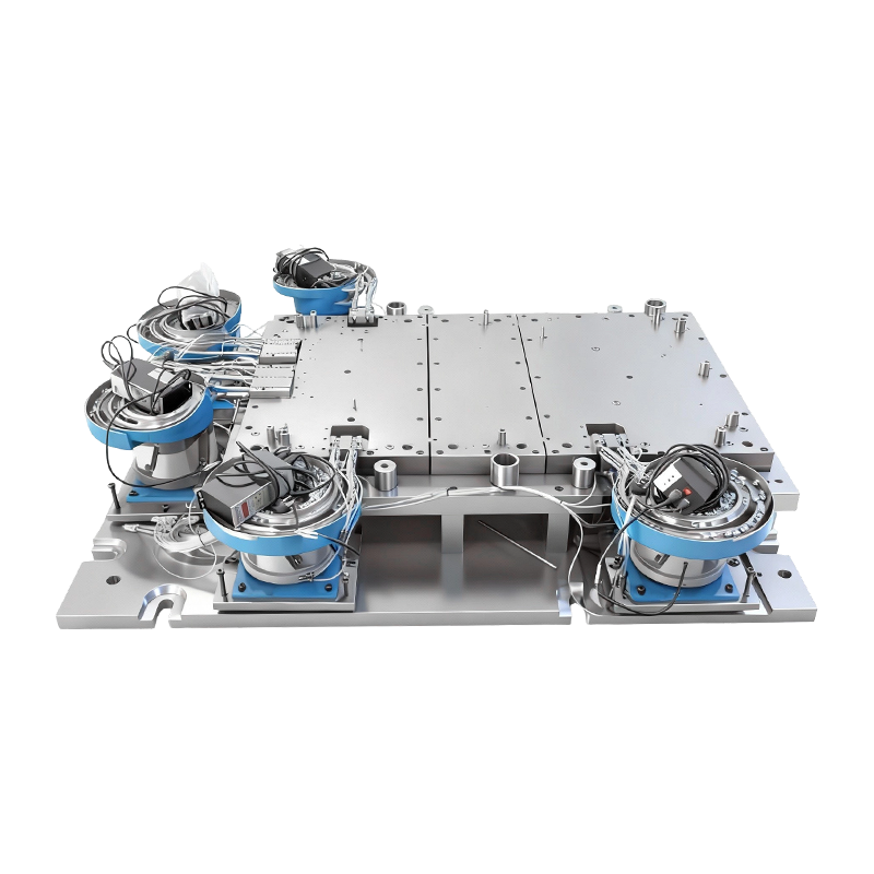
Automatic riveting mold for large computer machine base
This Automatic Riveting Mold for Large Computer Ma...
- E-mail us: [email protected]
- Call us: +86-139 1308 8972

Chen Siyi – Overseas Sales Manager
Home / Author / Chen Siyi – Overseas Sales Manager / Progressive Molds for Automotive Parts: Precision, Productivity, and Integrated Stamping Solutions
Progressive Molds for Automotive Parts: Precision, Productivity, and Integrated Stamping Solutions
2026-08-23
Automotive manufacturing is moving toward higher production volumes, tighter dimensional requirements, lighter components, and more complex powertrain and electric vehicle systems. These trends place exceptional demands on stamping dies. A die must do more than form metal into a desired shape. It must maintain repeatable accuracy throughout long production runs, support fast press cycles, minimize material waste, simplify maintenance, and protect the stability of the entire manufacturing line.
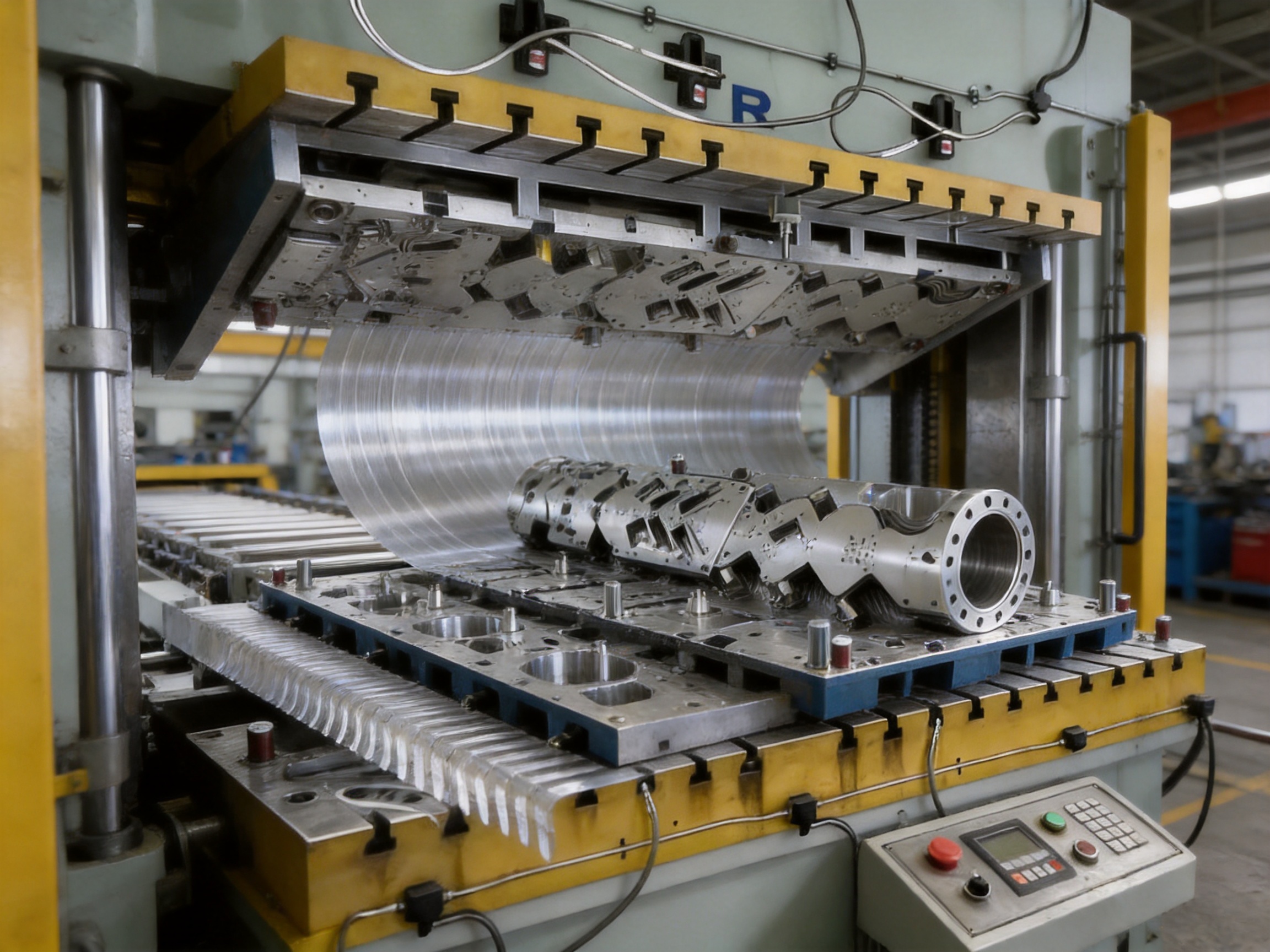
Progressive molds for automotive parts are designed to meet these demands by combining multiple forming operations within one coordinated tooling system. Instead of transferring a workpiece manually between separate machines, a progressive mold guides strip or coil material through a sequence of stations. Each station performs a defined operation, such as blanking, piercing, drawing, forming, bending, trimming, or sizing. By the time the material leaves the final station, it has become a finished or near-finished component ready for inspection and downstream assembly.
The progressive mold described in this article is engineered for automotive motor housings and small-sized automotive parts. It integrates stamping and forming operations into a streamlined continuous process that supports high-volume, precision production. Its design is particularly suitable for manufacturers producing components for automotive powertrain systems, electric vehicle drive units, servo-related assemblies, compressors, and other applications requiring consistent geometry and reliable production performance.
When compared with conventional single-operation tooling, this type of progressive mold offers important advantages in productivity, process consistency, floor-space utilization, and manufacturing control. It also benefits from high-hardness alloy steel components, modular construction, precision machining, and a manufacturing organization capable of combining die production with stamping automation. Together, these characteristics create a practical solution for companies seeking dependable automotive component production rather than a tool that only meets an initial dimensional target.
Progressive molds for automotive parts
Content
- 1 What Is a Progressive Mold for Automotive Parts?
- 2 Application in Automotive Motor Housings and Small Components
- 3 Integrated Stamping and Forming Process
- 4 Advantages Over Conventional Stamping Methods
- 5 High-Hardness Alloy Steel for Long-Term Durability
- 6 Modular Design for Maintenance and Rapid Replacement
- 7 Precision Design and Manufacturing Workflow
- 8 Manufacturing Capability and Technical Strength
- 9 Integrated Stamping Automation
- 10 Quality Control for Automotive Stamping Dies
- 11 Performance Benefits for Automotive Manufacturers
- 12 Material Utilization and Cost Efficiency
- 13 Installation, Commissioning, and Customer Support
- 14 How to Select the Right Progressive Mold Supplier
- 15 Recommended Customer Information for a Custom Project
- 16 Q&A: Progressive Molds for Automotive Parts
- 16.1 What types of automotive components can be produced with a progressive mold?
- 16.2 Is a progressive mold suitable for deep-drawn automotive housings?
- 16.3 How does the mold maintain dimensional accuracy during long production runs?
- 16.4 What is the benefit of modular die construction?
- 16.5 Can the tooling be connected to automatic stamping equipment?
- 16.6 What press capacity may be required?
- 16.7 How can progressive tooling reduce production costs?
- 16.8 What materials can be considered for the die components?
- 16.9 How long can a progressive mold operate?
- 16.10 Does the supplier provide only the die?
- 16.11 Why is tryout important before mass production?
- 16.12 What makes this type of tooling competitive?
- 17 Conclusion
- 18 References
- 19 Product: Progressive molds for automotive parts
What Is a Progressive Mold for Automotive Parts?
A progressive mold, also known as a progressive stamping die, is a precision tool containing several stations arranged in a continuous sequence. A metal strip is fed through the die by a controlled feeding system, and the press completes one or more operations at each stroke. With every press cycle, a new part or partially formed component advances from one station to the next.
The process begins with the loading of coil or strip material. The feeding mechanism advances the material by a predetermined pitch. Pilot pins, guides, and locating features then position the strip accurately before the upper die descends. Depending on the component design, the first stations may perform piercing or preliminary blanking. Subsequent stations can carry out drawing, coining, bending, forming, trimming, and calibration. The final station may separate the finished part from the carrier strip or leave it connected for automatic transfer to a secondary operation.
For automotive motor housings and similar small parts, the progressive approach is valuable because the component may require several carefully coordinated operations. A housing can need a combination of deep drawing, wall forming, edge trimming, hole piercing, surface sizing, and dimensional calibration. Completing these operations in one integrated tooling system reduces the number of handling steps and improves the relationship between each operation.
The die is not simply a collection of independent stations. Its performance depends on the interaction of the entire system. Strip layout, material utilization, forming sequence, press capacity, blank-holder behavior, clearance, lubrication, feeding accuracy, and scrap management must all be evaluated together. A well-designed progressive mold therefore begins with process engineering rather than only with the machining of individual die components.
Application in Automotive Motor Housings and Small Components
Automotive motor housings must often satisfy demanding requirements related to roundness, wall thickness, concentricity, surface quality, and assembly fit. These requirements apply to housings used in electric motors, actuators, compressors, powertrain systems, and other electromechanical assemblies. Even a small dimensional deviation can affect bearing seating, rotor clearance, sealing performance, vibration levels, heat transfer, or the alignment of mating components.
A progressive mold for this application is designed to maintain a controlled forming sequence. Early operations establish the basic blank and guide the material. Drawing stations gradually develop the cylindrical or shaped body while controlling deformation. Later stations refine the profile, establish holes or functional openings, remove excess material, and calibrate critical surfaces. This staged approach helps reduce sudden deformation and supports a more stable distribution of strain through the workpiece.
For small automotive parts, the same principle applies even when the component is not a motor housing. Brackets, shields, covers, connectors, support plates, structural inserts, and other stamped parts may require multiple operations. By integrating those operations into one die, manufacturers can reduce intermediate storage, decrease the risk of incorrect part orientation, and improve production traceability.
The tooling can be tailored to the material grade and thickness required by the customer. Automotive components may be produced from carbon steel, stainless steel, galvanized steel, high-strength steel, aluminum alloys, copper alloys, or other engineering materials. Each material behaves differently during cutting and forming. The die design must account for tensile strength, elongation, springback, work hardening, surface coating, friction, and required forming force.
For deep-drawn components, the relationship between blank diameter, draw ratio, corner radius, punch geometry, die radius, clearance, lubrication, and holding force is especially important. If the drawing sequence is too aggressive, the part may develop wrinkles, tearing, excessive thinning, or distortion. If the sequence is too conservative, the die may require unnecessary stations or produce inefficient material utilization. The purpose of the engineering process is to achieve the required geometry with a practical balance of quality, speed, tool life, and cost.
Integrated Stamping and Forming Process
The primary advantage of this progressive mold is its integrated stamping and forming process. Several operations are consolidated into a single production route, allowing the press to perform a repeatable sequence without repeated manual intervention. This integration is particularly useful in high-volume automotive production, where a small reduction in cycle time can create a significant annual output increase.
A typical process may include the following stages:
1. Strip entry and alignment: The coil strip enters the die through guide equipment that controls lateral position and elevation.
2. Pilot positioning: Pilot pins or comparable locating features correct small feeding deviations and ensure that each station receives the material in the correct position.
3. Initial blanking or piercing: The strip is prepared for forming, and nonfunctional material may be removed to create openings or establish the required blank profile.
4. Preliminary forming: The material begins to take the shape of the housing or component while deformation is distributed across the forming stations.
5. Deep drawing or progressive drawing: The workpiece is drawn in controlled stages to achieve the required depth, diameter, or profile.
6. Secondary piercing and forming: Holes, slots, steps, beads, flanges, or other functional features are produced after the material has reached a suitable intermediate shape.
7. Trimming and calibration: Excess material is removed, and critical surfaces are sized to improve dimensional accuracy and assembly compatibility.
8. Part separation and discharge: The finished part is separated from the carrier and transferred for inspection, cleaning, packaging, or a subsequent operation.
Not every product requires all of these operations, and the exact sequence depends on the component drawing and material specification. However, the principle remains the same: each station contributes to a controlled and measurable transformation of the material.
Integrated processing also reduces the number of times a part is picked up, repositioned, or placed into a separate fixture. Every manual transfer creates opportunities for scratches, dents, orientation errors, contamination, and dimensional variation. A progressive mold minimizes these risks by maintaining a controlled path from raw strip to finished component.
Advantages Over Conventional Stamping Methods
Higher Production Efficiency
Progressive tooling is well suited to high-volume production because it can produce a part during every press cycle after the line reaches its operating sequence. The press does not need to stop between individual forming steps. This continuous operation can significantly improve output compared with a series of independent dies requiring separate loading and unloading.
Higher efficiency is not limited to press speed. It also includes reduced handling, fewer intermediate inspections, less work-in-process inventory, and lower setup frequency. A manufacturer can operate a coordinated production cell rather than managing multiple disconnected processes.
Consistent Dimensional Quality
Because the workpiece remains connected to the strip during most or all of the forming sequence, each operation is referenced to a controlled material path. This helps maintain repeatability between stations. The use of pilot pins, guide plates, precision punches, and accurately machined die sections further improves positional stability.
For motor housings, consistency in wall thickness and fitting surfaces is particularly important. A stable forming sequence can help ensure that mating features are produced within the required tolerance range. Consistent geometry also simplifies downstream assembly and reduces adjustment work.
Reduced Labor and Handling Risk
Traditional multi-die processes often require operators or transfer equipment to move parts between operations. Progressive molds reduce this requirement. Less handling can lower direct labor demand while also reducing the possibility of part mixing, incorrect orientation, and damage caused by repeated loading.
Automation can be integrated with the press, feeder, lubricant system, inspection equipment, and discharge mechanism. This supports a more predictable production environment and allows operators to focus on process supervision, quality verification, and preventive maintenance.
Better Use of Factory Space
A sequence of separate presses and dies may require substantial floor space. A progressive mold consolidates multiple operations into one tooling system and can therefore reduce the footprint of the production line. This is valuable for factories seeking to increase capacity without expanding the building or adding a large number of machines.
Lower Long-Term Process Variation
When operations are separated, variations from one machine or fixture can accumulate. A progressive mold keeps related operations in one coordinated system. Once the die is properly debugged and the press parameters are established, the process can be repeated with fewer independent variables.
Improved Production Traceability
A continuous process makes it easier to connect raw material batches, press settings, tooling conditions, inspection records, and finished components. This is important for automotive supply chains, where customers often expect documented control of materials, dimensions, and process performance.
High-Hardness Alloy Steel for Long-Term Durability
Progressive dies operate under repeated impact, compressive loading, sliding contact, cutting forces, and friction. The most heavily loaded areas include punches, die inserts, forming surfaces, guide components, stripper plates, and cutting edges. If these components wear too quickly, the die may lose dimensional accuracy, increase burr formation, or require frequent adjustment.
The mold described here uses high-hardness alloy steel components selected for wear resistance and long-term stability. Alloy tool steels can provide a strong combination of hardness, toughness, compressive strength, and resistance to repeated contact. The appropriate grade and heat-treatment condition depend on the material being stamped, the forming operation, expected production volume, and the geometry of the component.
Hardness alone is not sufficient. A die component that is extremely hard but too brittle may crack or chip under impact. Conversely, a component with insufficient hardness may deform or wear rapidly. Effective tooling design balances hardness with toughness and uses different materials or treatments where necessary. Cutting edges may require high wear resistance, while larger structural components may require greater toughness and resistance to fatigue.
Accurate heat treatment is therefore an essential part of die manufacturing. Components must be processed to achieve the required mechanical properties while controlling distortion. After heat treatment, precision grinding, wire cutting, or additional machining may be required to restore critical dimensions and surface relationships.
Wear-resistant components provide several competitive benefits. They help maintain stable part dimensions over long production runs, reduce the frequency of die correction, extend the time between maintenance events, and support more predictable production planning. For high-volume automotive manufacturing, these benefits can be more important than the initial purchase price of the die alone.
Modular Design for Maintenance and Rapid Replacement
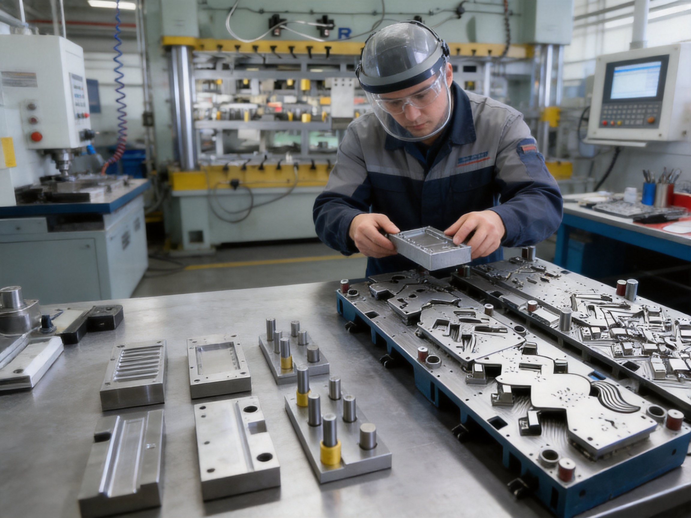
Automotive production lines cannot tolerate unnecessary downtime. If a die must be removed from the press for every minor repair, maintenance costs can quickly become significant. A modular progressive mold addresses this concern by dividing key working areas into replaceable sections or inserts.
Modular construction allows worn or damaged components to be removed and replaced without rebuilding the entire die. Depending on the design, replaceable elements may include punches, die inserts, forming blocks, trimming sections, guide components, stripper elements, or other high-wear parts. This design approach also makes it easier to keep spare components prepared for planned maintenance.
Rapid replacement has several advantages. First, it reduces the time needed to restore the die to production. Second, it limits the repair to the affected area rather than disturbing stable parts of the tooling. Third, it makes maintenance more predictable because common wear components can be monitored and replaced before they cause a quality issue.
Modularity also supports future product changes. Automotive components may be revised to accommodate new motors, sensors, batteries, mounting systems, or vehicle platforms. A modular die can sometimes be adapted by changing selected inserts or stations instead of manufacturing a completely new die. The feasibility of such changes depends on the original design and the degree of geometry variation, but the modular concept provides valuable flexibility.
Maintenance planning should include regular cleaning, lubrication, inspection of guide elements, checking of cutting clearances, verification of fasteners, and monitoring of critical dimensions. Operators should also inspect for burr growth, unusual noise, uneven wear, material scratching, part distortion, and changes in press load. These symptoms can indicate tool wear or a feeding problem before a major failure occurs.
Precision Design and Manufacturing Workflow
The performance of a progressive mold depends heavily on the quality of its design and manufacturing workflow. A reliable process typically begins with a detailed review of the customer’s component drawing, material specification, annual volume, press characteristics, quality requirements, and downstream assembly conditions.
Engineering Review
During the engineering review, the die maker evaluates the part geometry for manufacturability. Areas of concern may include deep draw ratios, sharp corners, narrow ribs, close hole-to-edge distances, thin sections, difficult springback zones, and features that cannot be formed in the proposed sequence. If necessary, the die design can be adjusted to improve forming reliability while preserving the functional requirements of the part.
Strip Layout Development
Strip layout is one of the most important stages in progressive die design. It determines how the part is oriented, how much carrier material is needed, where each operation occurs, and how efficiently the raw material is used. A strong layout balances material utilization with strip strength and station accessibility.
If the carrier is too narrow or too weak, the strip may deform during feeding. If it is too wide, material waste may increase. If operations are placed in an inefficient order, the component may become unstable before the final forming stages. Engineers therefore evaluate pitch, carrier design, scrap evacuation, forming direction, pilot locations, and press stroke requirements together.
Three-Dimensional Die Modeling
Three-dimensional modeling helps engineers verify clearances, component movement, forming interference, fastener access, maintenance space, and the relationship between upper and lower die assemblies. It also supports simulation of the forming sequence and allows potential problems to be identified before machining begins.
Digital modeling can be used to examine material flow and anticipate risks such as wrinkling, tearing, excessive thinning, springback, and collision between forming elements. Although physical tryout remains important, careful digital preparation can reduce the number of correction cycles required during commissioning.
Precision Machining
After design approval, die components are manufactured using precision machining equipment. The company’s equipment base includes imported wire cutting machines, CNC machining centers, and more than ten grinding machines of different sizes. This combination supports the production of complex cavities, accurate cutting profiles, hardened inserts, precision plates, and closely matched forming surfaces.
Wire electrical discharge machining is especially useful for producing intricate profiles, narrow slots, fine cutting edges, and hardened steel components that would be difficult to machine using conventional cutting tools. CNC machining centers support efficient production of die plates, pockets, mounting features, guide locations, and three-dimensional forming surfaces. Grinding operations then refine critical dimensions, flatness, parallelism, and surface finish.
Assembly and Alignment
Precision machining must be followed by careful assembly. A progressive die contains many interacting elements, and a small alignment error can cause accelerated wear, poor cutting quality, feeding instability, or part deformation. Experienced technicians check the relationship between guide posts, guide bushings, punches, die inserts, stripper plates, forming blocks, and carrier surfaces.
Assembly also includes verification of clearances and movement. Each moving element must travel smoothly without interference. Cutting edges must meet correctly, forming surfaces must contact as intended, and replaceable modules must be secured with accurate locating features. These checks are essential before the die is installed in a production press.
Press Tryout and Debugging
Die tryout converts the design into a stable production process. Skilled operators and debugging personnel test the tooling under controlled conditions, gradually adjusting feeding, stroke, pressure, lubrication, timing, and other parameters. Sample parts are inspected for dimensions, surface quality, burrs, cracks, wrinkles, thinning, and overall assembly fit.
Debugging may require changes to forming radii, clearances, pilots, strippers, guide surfaces, or material flow controls. The goal is not simply to produce one acceptable sample. The goal is to achieve a stable process that continues to produce acceptable parts across a realistic production run.
| Process Area | Typical Control Focus | Customer Benefit |
|---|---|---|
| Product and process review | Material, geometry, tolerances, volume, and press conditions | Reduced design risk and better production suitability |
| Strip layout | Station sequence, carrier strength, pitch, and material utilization | Stable feeding and lower material waste |
| Precision machining | Profiles, pockets, forming surfaces, and critical dimensions | Accurate interaction between die components |
| Heat treatment and grinding | Hardness, toughness, distortion control, and surface finish | Longer tool life and dimensional stability |
| Assembly and alignment | Clearance, parallelism, movement, and component positioning | Reliable operation and reduced wear |
| Tryout and debugging | Part quality, press parameters, material flow, and repeatability | Faster production launch and fewer quality interruptions |
| Maintenance planning | Wear monitoring, spare inserts, cleaning, and replacement intervals | Lower downtime and improved lifecycle economics |
Manufacturing Capability and Technical Strength
Suzhou Shuangqisi Mold Equipment Co., Ltd. is a professional manufacturer integrating stamping die design, manufacturing, hardware part production, and service. Its technical organization includes 60 technical staff, supported by experienced operators and debugging personnel. This structure enables the company to manage the complete process from initial tooling concept through machining, assembly, tryout, and customer support.
The company operates a broad range of manufacturing resources, including imported wire cutting machines, CNC machining centers, more than ten grinding machines of various sizes, and 25 punch presses ranging from 80 tons to 400 tons. This equipment base allows the organization to manufacture and test tooling for a wide variety of component sizes, materials, and forming requirements.
The availability of multiple press capacities is useful during die development. A mold can be tested under suitable load conditions rather than being limited to a single machine type. Press resources also provide practical support for stamping hardware parts and confirming whether the finished die performs as expected in production-like conditions.
The company has approximately 15 years of experience in the mold industry. During this period, it has served customers connected with servo drives, compressors, new energy vehicles, and other industrial sectors. Its main clients include Anter Group, Ousheng Electric, Dongbei Group, and Huichuan Technology. These applications require dependable tooling because stamped parts often function within electromechanical systems where dimensional accuracy and repeatability are essential.
In 2016, the company invested in and established Suzhou Keshuang Intelligent Technology Co., Ltd., which focuses mainly on stamping automation equipment. This relationship strengthens the company’s ability to offer more than a standalone die. Customers can receive a coordinated solution involving progressive tooling, feeding systems, stamping automation, production equipment, and process support.
The combination of die manufacturing and automation capability is a meaningful competitive advantage. Tooling and automation must work together. A die may be precisely manufactured, but the production system can still suffer if the feeder is unstable, the strip is not aligned, the discharge system is poorly coordinated, or sensors do not detect abnormal conditions. Integrated engineering helps reduce these compatibility problems.
Integrated Stamping Automation
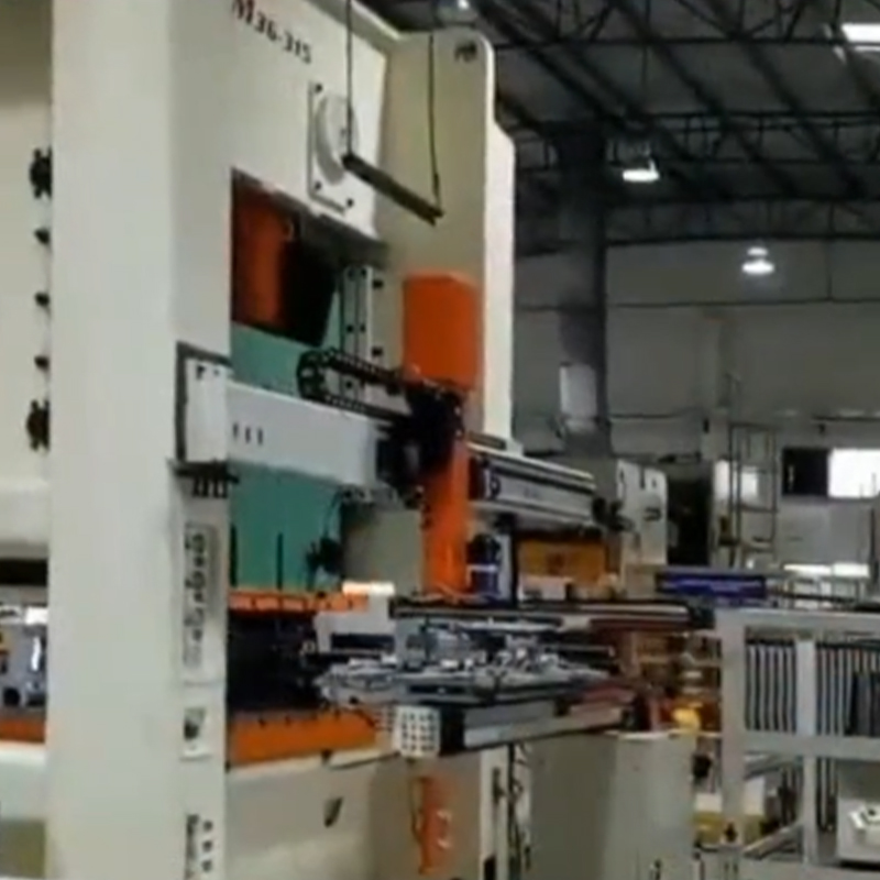
Automation is increasingly important in automotive component production because it supports consistent cycle times, reduces manual handling, improves workplace safety, and creates a more measurable production process. A progressive mold can be connected to automatic decoilers, straighteners, servo feeders, lubrication units, transfer systems, sensors, scrap conveyors, part collectors, and inspection devices.
A servo feeder can control the material pitch with high repeatability and can be synchronized with the press. Sensors can monitor strip presence, misfeed conditions, die protection, part ejection, and abnormal movement. Scrap handling equipment can remove skeleton material and piercing waste from the production area, reducing the risk of accumulation around the die.
Automation also supports production data collection. Depending on the system configuration, manufacturers may record press cycles, downtime events, alarm conditions, output quantity, and maintenance information. These data can be used to identify recurring stoppages, plan preventive maintenance, and compare actual performance with production targets.
For customers that require a complete production solution, the company can provide turnkey support for stamping molds and stamping automation. It can also invest in related production equipment according to customer requirements. This approach is useful for manufacturers that want to reduce the number of separate suppliers involved in a new line installation.
A coordinated solution can shorten communication paths during commissioning. If a feeding problem occurs, the die structure and automation settings can be reviewed together. If a part is not discharged correctly, the tooling and automation interfaces can be evaluated as one system. This integrated responsibility can make troubleshooting faster and reduce uncertainty during production launch.
Quality Control for Automotive Stamping Dies
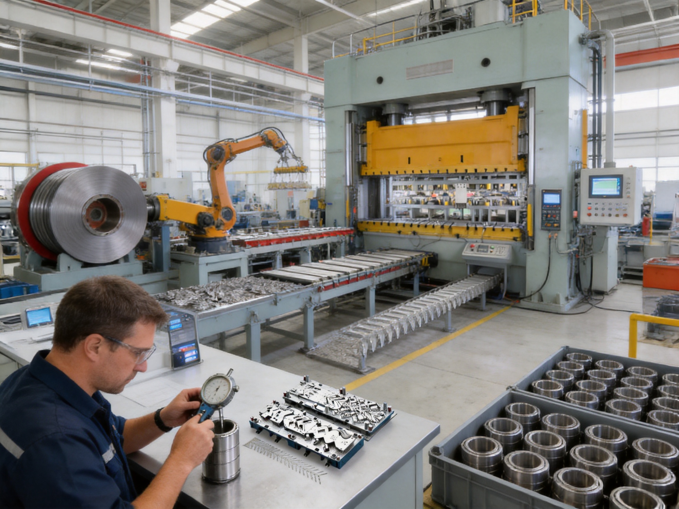
Quality control must cover both the die itself and the components it produces. A tooling supplier should verify raw material certificates, component dimensions, hardness, surface condition, assembly accuracy, and operational performance. The exact inspection plan depends on the customer’s requirements, but several controls are commonly important.
Die plates and inserts should be measured for dimensional accuracy, flatness, parallelism, and locating relationships. Punches and die openings should be checked for correct clearance and profile. Forming surfaces should be inspected for smoothness and consistency because rough or mismatched surfaces can mark the material or create uneven deformation.
During tryout, sample parts should be examined using suitable gauges and measurement equipment. Critical dimensions may include outside diameter, inside diameter, height, wall thickness, flange dimensions, hole position, roundness, concentricity, and surface profile. Functional fit checks can be carried out using mating components or approved inspection fixtures.
Visual inspection is also valuable. Scratches, dents, cracks, wrinkles, burrs, galling, and material pickup can reveal process problems that are not immediately obvious from dimensional data. A high-quality production process uses both measurement and visual evaluation rather than relying on one type of inspection alone.
Process capability should be considered when the part is intended for mass production. An isolated conforming sample does not demonstrate that the process is stable. Repeated samples from a continuous run provide more useful information about variation, tool wear, feeding consistency, and material behavior.
Documentation supports long-term service. Die drawings, component lists, spare-part information, inspection records, press settings, lubrication recommendations, and maintenance instructions can help the customer operate the tooling correctly. Clear documentation also makes future repair and replacement more efficient.
Performance Benefits for Automotive Manufacturers
Stable Wall Thickness
Controlled multi-stage forming helps distribute deformation more evenly. This is important for housings and deep-drawn parts, where excessive thinning in one area may weaken the component or affect its functional performance. A carefully developed drawing sequence can improve the consistency of the formed wall and reduce the risk of localized failure.
Precise Fitting Surfaces
Automotive housings frequently include surfaces that must mate with bearings, covers, seals, brackets, motors, or other precision parts. Progressive forming, trimming, and calibration stations can be designed around these functional surfaces. Stable fitting geometry can improve assembly efficiency and reduce the need for manual correction.
Lower Downtime
Wear-resistant materials and modular replacement sections support longer operating periods between major maintenance events. When maintenance is required, replaceable inserts can reduce repair time. The result is better equipment availability and more predictable production scheduling.
Support for Mass Production
The mold is designed for continuous, high-volume operation. Its value is greatest when a manufacturer needs a substantial number of consistent parts over an extended program life. By combining rapid cycling with controlled accuracy, the tooling can help reduce the cost per part while maintaining the quality expected in automotive supply chains.
Adaptability to New Energy Vehicles
Electric vehicles and hybrid vehicles use many stamped components in motors, compressors, power electronics, battery-related systems, cooling assemblies, and structural modules. These parts may be compact but require precise interfaces. A progressive mold with deep-drawing and forming capability can support the production of such components while allowing process engineering to be adapted to new designs.
Material Utilization and Cost Efficiency
Material cost is a major factor in automotive stamping. A large production program may consume many tons of coil material, so even a small improvement in strip utilization can generate meaningful savings. Strip layout engineers seek to minimize unnecessary carrier width, optimize part orientation, reduce scrap bridges, and arrange stations efficiently.
Material utilization must be balanced against process stability. A layout that saves material but creates a weak carrier may cause feeding errors or part deformation. Similarly, reducing the distance between parts may make cutting more difficult or limit the space needed for pilots and forming features. The best layout is not always the one with the smallest theoretical scrap percentage; it is the one that delivers reliable production at an acceptable total cost.
Integrated tooling can also reduce indirect costs. Fewer separate dies mean fewer tool changes, less storage, fewer setup operations, and less internal transportation. Reduced handling can lower the risk of damage and simplify production planning. When automation is included, labor allocation and line balancing can be improved as well.
Lifecycle cost should be considered when comparing progressive molds with lower-cost alternatives. A less expensive die may require more frequent sharpening, adjustment, insert replacement, or manual intervention. It may also produce more rejects or operate at a lower practical speed. A durable, accurately engineered mold can offer better value over the full production program even if its initial investment is higher.
Installation, Commissioning, and Customer Support
Successful installation begins with confirming the press specifications. Important factors include nominal capacity, shut height, slide dimensions, stroke length, press speed, bolster size, feeding direction, coil width, material thickness, and available automation interfaces. The die must be compatible with the customer’s equipment and production environment.
During commissioning, the tooling should be installed according to documented procedures. The press should be checked for alignment, die protection should be activated, and the feeder should be synchronized before production speed is increased. Initial runs are commonly performed at a reduced speed so that operators can observe strip movement, forming behavior, scrap removal, and part discharge.
Customer personnel should receive practical instruction on die operation and maintenance. Training may cover lubrication, cleaning, inspection points, safe die handling, common fault conditions, spare-component replacement, and procedures for restarting after a stoppage. Good training helps protect the investment and reduces avoidable tooling damage.
Technical support remains important after delivery. Production conditions can change because of material suppliers, coil properties, press adjustments, lubrication choices, or product revisions. A capable tooling partner should be able to analyze performance concerns and recommend adjustments or replacement components when necessary.
How to Select the Right Progressive Mold Supplier
Automotive manufacturers should evaluate more than a supplier’s ability to machine a die. The supplier should demonstrate competence in product analysis, progressive process planning, material selection, precision machining, heat treatment management, assembly, tryout, and production support.
Experience with similar components is valuable. A supplier familiar with motor housings, deep-drawn parts, servo-related components, compressors, and new energy vehicle applications is more likely to recognize common forming risks and practical production requirements.
Equipment capability is another important consideration. Wire cutting, CNC machining, grinding, inspection, and press tryout resources should be appropriate for the size and accuracy of the project. The supplier should also have enough technical personnel to manage design changes, debugging, and customer communication.
Automation capability can distinguish a tooling manufacturer from an integrated production partner. If the customer requires automatic feeding, scrap handling, sensors, or a complete stamping cell, it is helpful when the die supplier can coordinate these elements directly.
Finally, the supplier should explain its approach to maintenance and lifecycle service. Modular components, spare-part availability, clear documentation, and technical response can have a major impact on the total value of the project.
Recommended Customer Information for a Custom Project
To develop an accurate proposal, a customer should provide the latest component drawings and three-dimensional data whenever available. The material grade, thickness, surface treatment, mechanical properties, and coil specifications should also be identified.
Production information should include annual volume, required cycle time, expected program duration, target yield, allowable scrap, packaging method, and downstream assembly requirements. Press information should cover capacity, stroke, shut height, slide size, bolster dimensions, speed range, and feeder compatibility.
Quality requirements should identify critical dimensions, tolerances, surface expectations, burr limits, inspection methods, and any special customer standards. Information about existing equipment, factory layout, automation preferences, and maintenance capabilities can further improve the proposed solution.
The more complete the initial information, the more accurately the supplier can determine the number of stations, forming sequence, press requirement, die size, material utilization, automation configuration, and expected production performance.
Q&A: Progressive Molds for Automotive Parts
What types of automotive components can be produced with a progressive mold?
Progressive molds can produce many types of sheet-metal components, including motor housings, covers, brackets, shields, support plates, structural parts, compressor components, servo-related hardware, and small electric vehicle parts. The exact suitability depends on the component geometry, material, thickness, required forming depth, and production volume.
Is a progressive mold suitable for deep-drawn automotive housings?
Yes. Progressive tooling can perform deep drawing in multiple controlled stages. A staged process is often preferable to one aggressive drawing operation because it distributes deformation and reduces the risk of tearing, wrinkling, and excessive thinning. The final design must be validated against the material and required geometry.
How does the mold maintain dimensional accuracy during long production runs?
Dimensional stability is supported by precision machining, high-hardness alloy steel components, accurate guide systems, controlled clearances, suitable heat treatment, and a carefully debugged forming sequence. Regular inspection and timely replacement of wear components are also essential.
What is the benefit of modular die construction?
Modular construction allows selected worn or damaged components to be replaced without rebuilding the complete die. This can reduce maintenance time, limit production interruptions, simplify spare-part management, and provide greater flexibility for future product modifications.
Can the tooling be connected to automatic stamping equipment?
Yes. The progressive mold can be integrated with automatic feeders, decoilers, straighteners, lubrication equipment, scrap conveyors, sensors, transfer systems, and discharge equipment. An integrated tooling and automation provider can help coordinate these interfaces during commissioning.
What press capacity may be required?
The required press capacity depends on material strength, thickness, blank size, cutting perimeter, drawing force, forming sequence, die dimensions, and safety margin. The supplier should calculate the estimated force and confirm compatibility with the customer’s press. The manufacturer’s available press range of 80 to 400 tons supports a broad selection of stamping applications.
How can progressive tooling reduce production costs?
It can reduce costs through faster cycle times, lower manual handling, fewer separate setups, improved material utilization, reduced work-in-process inventory, lower part variation, and less downtime. The actual savings depend on production volume, component design, press efficiency, and maintenance practices.
What materials can be considered for the die components?
High-hardness alloy tool steels are commonly used for punches, die inserts, forming surfaces, and other highly stressed components. Material selection depends on the stamped material, production volume, wear conditions, impact loading, and required service life. Heat treatment and finishing processes must be matched to the selected steel.
How long can a progressive mold operate?
Service life varies widely according to material, thickness, production volume, press speed, lubrication, maintenance, and die design. Wear-resistant components, proper alignment, good process control, and timely maintenance can substantially extend operational life. A supplier should provide maintenance recommendations based on the specific application.
Does the supplier provide only the die?
The company can provide stamping molds and stamping automation solutions. It can also support related production equipment investment according to customer requirements. This creates the possibility of receiving a coordinated solution rather than sourcing every part of the production system independently.
Why is tryout important before mass production?
Tryout confirms that the die, press, material, feeder, lubrication, and discharge system work together correctly. It identifies problems such as wrinkles, cracks, burrs, feeding errors, interference, or dimensional drift. Proper debugging helps ensure that the tool is stable under realistic production conditions.
What makes this type of tooling competitive?
Its competitive strengths include continuous integrated processing, high-volume capability, precision forming, wear-resistant alloy steel construction, modular maintenance, experienced technical personnel, precision manufacturing equipment, available press tryout capacity, and access to stamping automation expertise. These advantages address both initial quality and long-term production performance.
Conclusion
Progressive molds for automotive parts provide a practical foundation for high-volume, precision metal forming. For automotive motor housings and small-sized components, the combination of continuous stamping, controlled drawing, secondary forming, trimming, and calibration can deliver consistent geometry while reducing handling and production complexity.
The mold described here is engineered around the needs of automotive powertrain, electric vehicle, servo, compressor, and related applications. High-hardness alloy steel components help resist wear and maintain dimensional accuracy. Modular construction supports rapid replacement and easier maintenance. A carefully developed manufacturing workflow, including strip layout, three-dimensional design, precision machining, grinding, assembly, tryout, and debugging, helps transform the tooling from a concept into a reliable production asset.
Suzhou Shuangqisi Mold Equipment Co., Ltd. strengthens this offering through its integrated capabilities in stamping die design, manufacturing, hardware part production, and automation. Its technical staff, precision equipment, range of 80-ton to 400-ton punch presses, industry experience, and cooperation with a dedicated stamping automation company enable it to support customers from tooling development through production implementation.
For manufacturers comparing progressive dies with conventional multi-step production methods, the most important evaluation should include total lifecycle value. Output, dimensional stability, maintenance time, material utilization, automation compatibility, technical support, and future adaptability all influence the success of an automotive stamping program. A well-engineered progressive mold can help manufacturers achieve faster production, fewer interruptions, better part consistency, and a more efficient path from raw material to finished automotive component.
References
1. American Society of Mechanical Engineers, standards and practices related to mechanical manufacturing equipment and tooling safety.
2. ASM International, technical references on tool steels, heat treatment, wear resistance, and metal forming.
3. Society of Manufacturing Engineers, publications on sheet-metal stamping, progressive die design, and production automation.
4. American Iron and Steel Institute, technical guidance on steel properties and sheet-metal forming behavior.
5. International Organization for Standardization, quality management principles for manufacturing and production control.
6. Automotive Industry Action Group, reference materials concerning automotive supplier quality and production process planning.
7. Standard engineering literature on deep drawing, blank-holder control, springback, material utilization, and progressive stamping processes.
8. Manufacturer-provided technical information concerning automotive motor housing molds, stamping die manufacturing capabilities, precision equipment, press capacity, and integrated automation services.
Product: Progressive molds for automotive parts
Previous Post
New Energy Vehicle Copper Busbar Stamping Parts for High-Voltage Electrical Systems
Next Post
Advanced Stamping Automation Equipment for Efficient, Reliable Metal Forming
Our Products.
Start Your Business with an OEM Manufacturer Right Here!

Provide global customers with complete turn-key solutions
through
innovation!
QUICK LINKS
CONTACT INFO.
-
 +86-139 1308 8972
 -

-
 No. 118 Yexin Road, Wujiang Economic Development Zone, Suzhou, China
Copyright © Suzhou Shuangqisi Mold Equipment Co., Ltd. All Rights Reserved. Custom Stamping Die Metal Stamping Die Manufacturers
