 English
 Español
 Deutsch
-
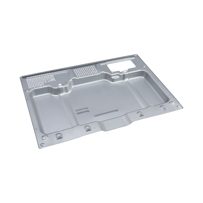
High-end oven stamping parts
Our High-end oven stamping parts are precision-man...
-
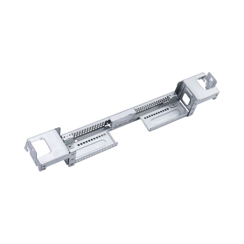
High-end large computer stamping parts
Our High-end large computer stamping parts are pre...
-
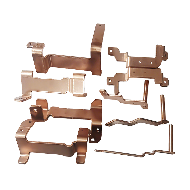
New energy vehicle copper busbar stamping parts
New energy vehicle copper busbar stamping parts ar...
-
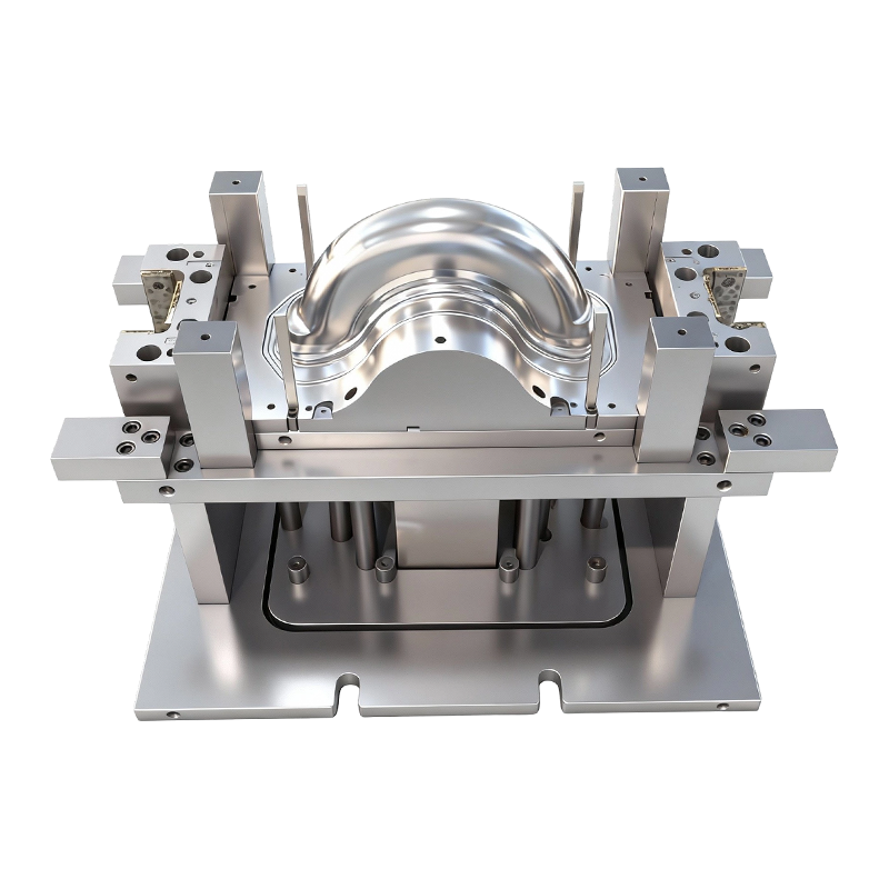
Deep drawing mold for front and rear wheels of two-wheeled electric vehicles
This Deep drawing mold for front and rear wheels o...
-
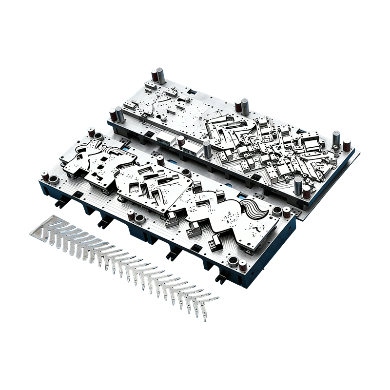
Progressive molds for automotive parts
This Continuous mold for automotive motor housing ...
- E-mail us: [email protected]
- Call us: +86-139 1308 8972

Chen Siyi – Overseas Sales Manager
Home / Author / Chen Siyi – Overseas Sales Manager / New Energy Vehicle Copper Busbar Stamping Parts for High-Voltage Electrical Systems
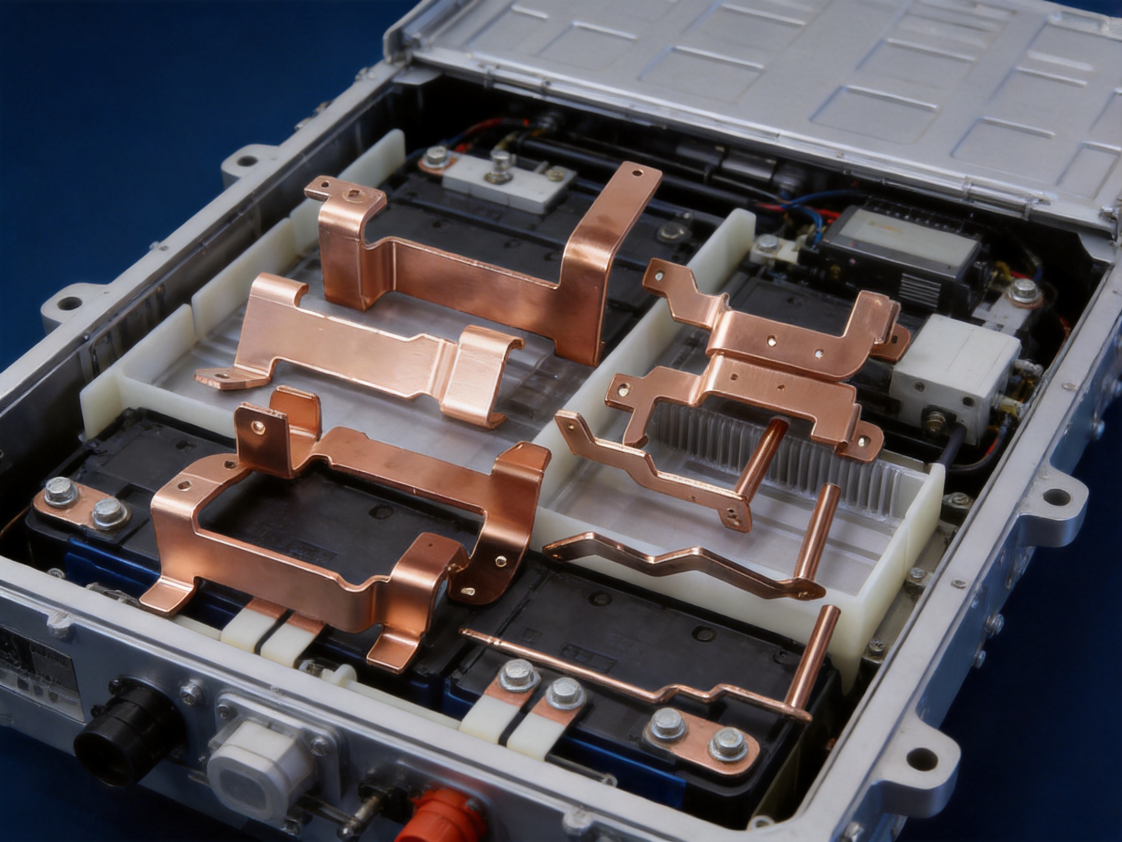
New Energy Vehicle Copper Busbar Stamping Parts for High-Voltage Electrical Systems
2026-09-04
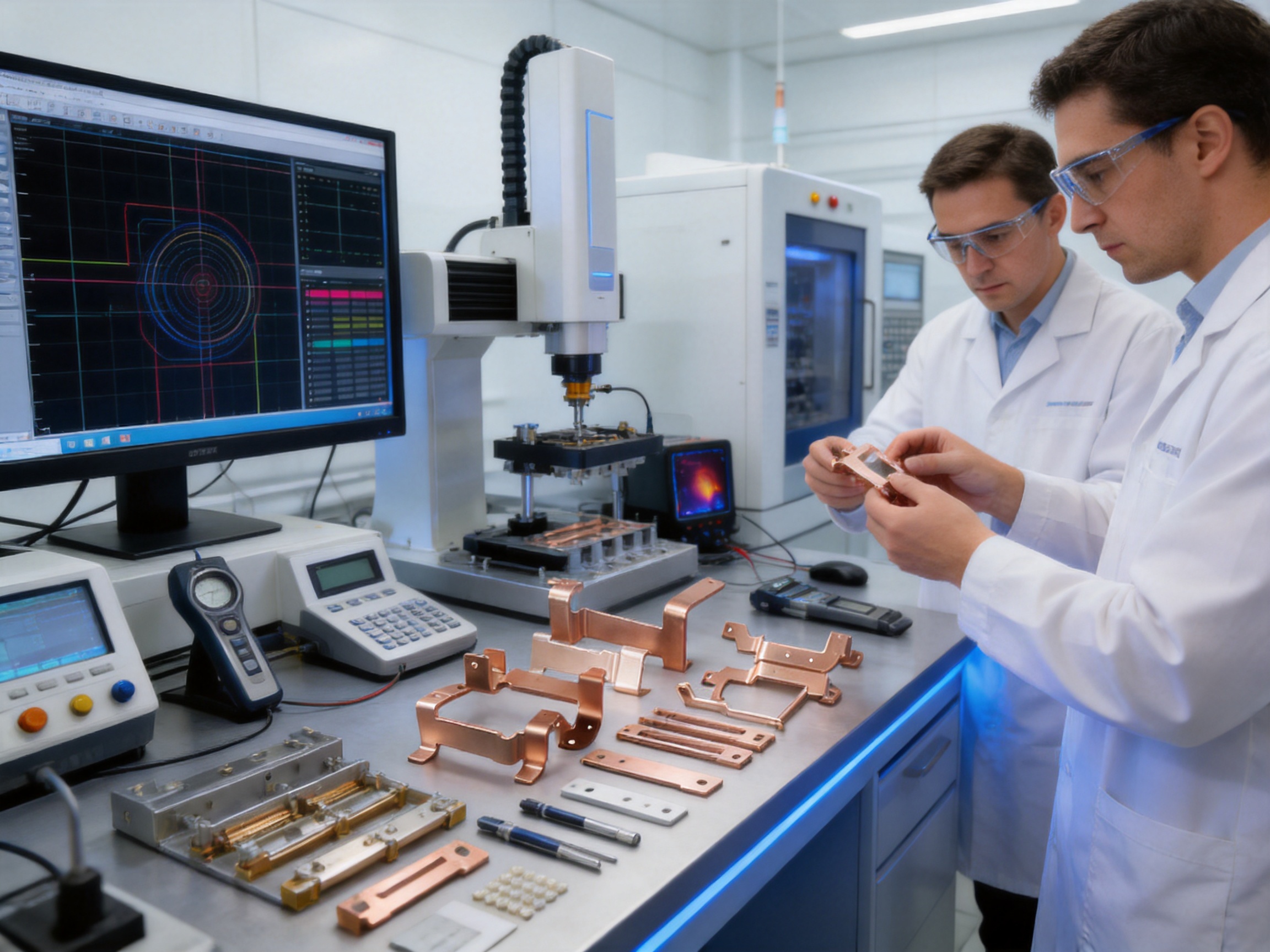
New energy vehicle copper busbar stamping parts are essential conductive components for the safe, efficient, and compact distribution of electrical power in electric vehicles, hybrid vehicles, battery systems, and related charging equipment. As vehicle electrification continues to develop, manufacturers are replacing many conventional cable assemblies with formed copper busbars that can carry high current through carefully controlled, low-resistance paths.
A copper busbar is more than a simple strip of metal. It is a precision-engineered electrical and mechanical part designed to connect batteries, battery management systems, inverters, drive motors, DC/DC converters, charging modules, fuse boxes, contactors, and other high-voltage components. Its shape, thickness, hole location, bend angle, surface finish, and insulation requirements must all be controlled to ensure reliable performance throughout the vehicle’s service life.
New energy vehicle copper busbar stamping parts combine the electrical conductivity of high-purity copper with the speed, repeatability, and dimensional control of precision metal stamping. Compared with manually cut, drilled, and bent components, stamped busbars can provide more consistent geometry, reduced assembly labor, improved space utilization, and better suitability for large-volume production.
Suzhou Shuangqisi Mold Equipment Co., Ltd. provides stamping die design, stamping die manufacturing, stamped metal parts, and stamping automation solutions for demanding industrial applications. Its experience in molds, high-speed machining, precision grinding, punch press production, and automation integration enables customers to obtain coordinated tooling and production support from one source.
Content
- 1 1. The Role of Copper Busbars in New Energy Vehicles
- 2 2. Product Construction and Material Selection
- 3 3. Advantages of Stamped Copper Busbars Over Conventional Wiring
- 4 4. Competitive Advantages of Precision Stamping Technology
- 5 5. Manufacturing Process for New Energy Vehicle Copper Busbar Stamping Parts
- 6 6. Manufacturing Equipment and Technical Capabilities
- 7 7. Quality Control for Automotive Copper Busbars
- 8 8. Surface Plating, Insulation, and Assembly Integration
- 9 9. Current-Carrying Capacity and Thermal Performance
- 10 10. Why Integrated Die and Automation Support Matters
- 11 11. Company Manufacturing Strengths
- 12 12. Design Recommendations for Better Busbar Production
- 13 13. Applications in Electric and Hybrid Vehicles
- 14 14. Cost and Lifecycle Benefits
- 15 15. Project Development and Customer Cooperation
- 16 16. Comparison of Copper Busbar Manufacturing Approaches
- 17 17. Environmental and Compliance Considerations
- 18 18. Frequently Asked Questions
- 18.1 Q1: What are new energy vehicle copper busbar stamping parts?
- 18.2 Q2: Which copper materials can be used?
- 18.3 Q3: What current range can these busbars support?
- 18.4 Q4: Why use a busbar instead of a wiring harness?
- 18.5 Q5: What surface treatments are available?
- 18.6 Q6: Can complex three-dimensional busbars be stamped?
- 18.7 Q7: What dimensional accuracy is possible?
- 18.8 Q8: How is burr quality controlled?
- 18.9 Q9: What press capacities are available?
- 18.10 Q10: Can the supplier provide automation as well as stamping dies?
- 18.11 Q11: What information should a customer provide for a quotation?
- 18.12 Q12: Are these busbars suitable for high-temperature and vibration environments?
- 19 19. Conclusion
- 20 References
- 21 Product: New energy vehicle copper busbar stamping parts
1. The Role of Copper Busbars in New Energy Vehicles
Electric vehicles require electrical systems capable of transferring large amounts of current between energy storage, power conversion, and propulsion components. In a conventional internal-combustion vehicle, many electrical circuits operate at relatively low voltage and moderate current. In an electric vehicle, the battery pack and power electronics may operate at several hundred volts, while current levels can reach hundreds or even thousands of amperes in specific applications.
These operating conditions place demanding requirements on every conductive connection. A busbar must have sufficiently low electrical resistance, adequate cross-sectional area, reliable contact surfaces, strong mechanical support, and resistance to vibration, moisture, corrosion, and thermal cycling. It must also fit within a restricted installation space, often alongside cooling channels, insulation barriers, sensors, connectors, and protective housings.
Copper is widely selected because it offers excellent electrical and thermal conductivity. High-purity grades such as C11000, C10100, and T2 copper can provide copper content of approximately 99.9 percent or higher, depending on the selected material standard. High conductivity allows current to pass with lower electrical loss, while high thermal conductivity helps transfer heat away from current-carrying areas.
Busbars may be used in battery modules, battery packs, power distribution units, charging systems, inverter connections, motor control assemblies, and high-voltage junction boxes. Their configurations vary according to the electrical architecture of the vehicle. Some are flat and relatively straight, while others incorporate multiple bends, stepped sections, terminal tabs, slots, bolt holes, contact areas, and mounting features.
Precision stamping makes it possible to produce these different geometries in a controlled and repeatable manner. Depending on the design, a part may be blanked, pierced, formed, bent, embossed, coined, or progressively shaped through several die stations. The manufacturing process is selected according to the material thickness, production quantity, dimensional requirements, bend complexity, and surface treatment plan.
New energy vehicle copper busbar stamping parts
2. Product Construction and Material Selection
2.1 High-Purity Copper Materials
The material selected for a copper busbar directly affects conductivity, heat generation, forming behavior, mechanical performance, and cost. C11000 copper is commonly associated with high conductivity and good forming performance. C10100 copper offers very high purity and is suitable for applications where electrical performance is particularly important. T2 copper is also widely used in industrial conductive components and can provide a practical balance between conductivity, availability, and manufacturing performance.
Material selection should not be based on conductivity alone. The stamping process must also account for copper hardness, temper condition, elongation, springback, thickness tolerance, and susceptibility to surface damage. A material that provides excellent conductivity but is difficult to form may require a different die structure, larger bend radius, additional forming stations, or a specialized process sequence.
For high-current applications, the busbar cross section is selected to control current density and temperature rise. A thicker or wider busbar can carry more current, but it may require greater forming force and more installation space. A successful design therefore balances current-carrying capacity, thermal performance, available packaging space, weight, material usage, and manufacturability.
2.2 Thickness and Cross-Sectional Design
Busbar thickness commonly varies according to current demand and packaging limitations. The required thickness is influenced by continuous current, peak current, ambient temperature, cooling conditions, allowable temperature rise, duty cycle, and the length of the conductive path. The design must also consider the strength required at fastening points and the risk of deformation during assembly.
Wide flat sections can improve current capacity without increasing thickness excessively. However, wide sections may be more difficult to bend accurately and may require larger die clearances. Narrow tabs and terminal areas may need local reinforcement, coining, or carefully controlled radii to prevent cracking and maintain reliable contact.
Designers should define critical dimensions clearly. These may include overall length, width, thickness, hole diameter, hole-to-edge distance, bend angle, bend position, flatness, parallelism, and terminal alignment. For precision applications, dimensional accuracy may be controlled within approximately ±0.05 to ±0.2 millimeters, depending on the feature and the production method.
2.3 Surface Treatment and Contact Reliability
Although bare copper has excellent conductivity, it can oxidize when exposed to air, moisture, heat, and contaminants. Surface treatments such as tin plating, nickel plating, or silver plating can improve corrosion resistance and stabilize the contact interface. Typical coating thicknesses may be approximately 3 to 5 micrometers, subject to the application, customer specification, and selected plating system.
Tin plating is often selected for a combination of corrosion protection, solderability, and cost efficiency. Nickel plating can provide strong resistance to heat and wear, while silver plating offers excellent conductivity and can be selected for specialized high-performance contact applications. The correct treatment depends on the electrical interface, temperature range, mating material, fastening method, and environmental exposure.
Surface treatment is not a substitute for correct stamping quality. Burrs, scratches, contamination, excessive forming marks, or poor edge conditions can reduce the effectiveness of a plating system. For this reason, deburring, cleaning, handling, and inspection should be integrated into the production plan.
3. Advantages of Stamped Copper Busbars Over Conventional Wiring
3.1 Lower Electrical Resistance
A properly designed copper busbar provides a direct and stable current path. Compared with a wiring harness containing multiple cables, crimped terminals, connectors, and routing loops, a busbar can reduce the number of connection points and shorten the conductive path. Fewer interfaces can reduce contact resistance and simplify the electrical layout.
Lower resistance helps reduce power loss and heat generation. This is especially important in high-voltage battery and propulsion systems, where even small increases in resistance can cause measurable energy loss during charging, acceleration, regenerative braking, or continuous operation.
3.2 Improved Heat Dissipation
Copper has thermal conductivity of approximately 385 watts per meter-kelvin, depending on the material grade and test condition. Its ability to distribute and dissipate heat can help maintain more stable operating temperatures around electrical connections.
Thermal performance depends on the complete assembly rather than the busbar alone. Contact pressure, mounting conditions, insulation, cooling airflow, liquid cooling structures, nearby components, and the duty cycle all influence temperature. Nevertheless, a copper busbar provides a highly conductive thermal path and can be designed to work effectively with the vehicle’s cooling architecture.
3.3 Better Space Utilization
Wiring harnesses must accommodate bending radii, protective sleeves, connector bodies, clips, and routing clearances. A shaped busbar can follow a defined three-dimensional path and occupy less space within a battery pack or power distribution assembly.
Compact packaging is especially valuable in new energy vehicles because battery systems compete for space with crash structures, cooling systems, passenger compartments, electronic control units, and charging hardware. A stamped busbar can incorporate mounting tabs, locating features, holes, and bends into one integrated component, reducing the number of separate parts.
3.4 Reduced Assembly Complexity
A busbar may replace several cables, terminals, brackets, and fastening operations. This can reduce assembly time and simplify production-line handling. It can also improve the repeatability of the finished electrical system because the connection geometry is defined by the stamped component rather than by manual cable routing.
When the tooling is correctly designed, each production cycle can create a consistent part with repeatable holes, edges, and formed sections. Automated feeding, transfer, inspection, and collection systems can further reduce manual handling and help maintain stable production output.
3.5 Consistent Mechanical Positioning
In a high-voltage assembly, the location of a conductive component must be controlled carefully to avoid interference with insulation barriers, adjacent terminals, covers, and other electrical paths. Stamped busbars can include precise locating holes, reference edges, and formed positioning features.
Consistent positioning supports automated assembly and helps maintain the designed electrical clearances and creepage distances. It also reduces the risk of installation variation that may occur when flexible cables are manually routed.
3.6 Suitability for Large-Volume Production
Stamping dies are well suited to repeat production. After die tryout and process validation, a progressive die, compound die, or transfer die can produce large quantities with relatively stable cycle times. This is an important advantage for automotive programs that require repeatable output over extended production periods.
Compared with machining each busbar individually, stamping can reduce cycle time and material processing cost for medium- and high-volume orders. The economic advantage becomes stronger when multiple operations are integrated into one tool and when automation reduces labor requirements.
4. Competitive Advantages of Precision Stamping Technology
4.1 Progressive Die Production
Progressive stamping is suitable when a copper busbar requires multiple operations in a continuous strip. The material advances through a sequence of stations, where the die may perform pilot positioning, piercing, notching, blanking, forming, bending, coining, and cut-off operations.
This approach supports high production efficiency and consistent part-to-part quality. It can also reduce the need to move semi-finished parts between separate machines. However, progressive die design requires careful control of strip layout, carrier strength, material utilization, station timing, punch clearance, forming sequence, and scrap discharge.
4.2 Compound Die Production
A compound die performs two or more cutting operations in one press stroke. It can be useful for flat busbar designs that require accurate external profiles and multiple holes. When hole-to-hole relationships and external dimensions are critical, compound tooling can reduce positional variation between separate operations.
Compound dies may be selected for parts with moderate complexity and stable production volumes. The final process choice depends on the required forming operations and the customer’s output targets.
4.3 Transfer and Multi-Stage Forming
Complex busbars may require several forming stages to achieve multiple bends without distortion. Transfer tooling can move individual blanks between stations, allowing each stage to perform a controlled operation. This can be useful for thick copper parts, three-dimensional geometries, and components with difficult terminal formations.
Multi-stage forming distributes the deformation and reduces the risk of cracking, twisting, and excessive springback. It also allows the die designer to control the direction of forming forces and provide sufficient support around holes and narrow sections.
4.4 Controlled Burrs and Edge Quality
Cutting direction and clearance have a direct effect on burr height, fracture zone, rollover, and edge quality. Excessive burrs can interfere with insulation, create assembly hazards, and reduce electrical clearance. Precision die design includes the selection of appropriate punch-to-die clearance, tool material, edge geometry, and maintenance intervals.
Where required, secondary deburring, brushing, tumbling, or controlled edge treatment can be added. The objective is to provide clean edges without removing excessive material or damaging the plated surface.
4.5 Dimensional Repeatability
Automotive electrical components often require stable dimensions across thousands or millions of pieces. Repeatability is supported by rigid die structures, accurate guide systems, precision-machined cavities, stable press settings, controlled material feeding, and regular inspection.
Dimensional control should be established through a documented inspection plan. Critical features can be checked by gauges, calipers, micrometers, optical measuring systems, coordinate measuring machines, or specialized fixtures. Statistical process monitoring may be used for features that have a direct effect on assembly performance.
5. Manufacturing Process for New Energy Vehicle Copper Busbar Stamping Parts
5.1 Engineering Review and Product Feasibility
Manufacturing begins with a review of the customer’s drawings, three-dimensional data, material specification, annual volume, packaging requirements, electrical ratings, surface treatment requirements, and quality standards. The engineering team evaluates whether the proposed geometry can be stamped efficiently and whether any features should be modified for better forming, tool life, or material utilization.
Important review points include minimum bend radius, hole proximity to bend lines, narrow sections, forming direction, required flatness, springback compensation, plating allowance, and inspection accessibility. Early design-for-manufacturing analysis can prevent expensive tooling changes after production has started.
For high-current busbars, the engineering review may also consider the relationship between cross-sectional area and current demand. While the tooling manufacturer does not replace the customer’s electrical design authority, manufacturing feedback can identify areas where the geometry may create unnecessary resistance, excessive heat concentration, or difficult assembly conditions.
5.2 Material Preparation
Copper coil or sheet is selected according to grade, thickness, temper, width, and surface condition. Incoming material should be checked against the approved specification. Important checks may include chemical composition documentation, thickness, width, flatness, surface cleanliness, hardness, and visible defects.
Clean material is particularly important for busbars that will later receive plating or another protective treatment. Oil, oxidation, scratches, or embedded particles may affect forming and surface finishing. Material storage should protect the copper from excessive humidity, contamination, and mechanical damage.
5.3 Die Design and Tool Development
The die is the core of the stamping process. A stamping die for a copper busbar may include guide pillars, guide plates, punches, die inserts, stripper components, lifters, pilots, forming blocks, bending components, sensors, and scrap-management features.
Tool designers determine the operation sequence based on the part geometry. A common sequence may begin with strip feeding and pilot positioning, followed by piercing, notching, partial forming, bending, coining, final blanking, and part separation. The sequence must prevent interference between the part and the tooling while maintaining strip strength until the appropriate cut-off stage.
Die clearances must be selected according to copper grade, thickness, hardness, and the required edge quality. Forming radii must account for material ductility and springback. Where necessary, forming may be performed progressively rather than in one severe operation.
5.4 Precision Machining of Die Components
After design approval, die components are produced using precision machining equipment. Wire cutting is useful for producing accurate profiles, narrow slots, and complex insert geometries. CNC machining centers can create die bases, pockets, mounting surfaces, and complex three-dimensional components. Grinding machines are used to achieve accurate thickness, flatness, parallelism, and surface finish on critical components.
Tool accuracy has a direct effect on finished-part quality. A die cavity that is slightly misaligned may cause uneven burrs, inconsistent hole positions, or an unwanted bend angle. For this reason, machining, grinding, inspection, and assembly must be coordinated carefully.
5.5 Die Assembly and Tryout
During assembly, individual die components are fitted, aligned, checked, and adjusted. The tool is then installed on a suitable punch press for tryout. Initial trials may use sample material to confirm strip progression, operation sequence, forming behavior, and part release.
Trial results are reviewed for dimensional accuracy, burr condition, surface marks, cracks, twisting, deformation, and feeding stability. Adjustments may include modifying clearances, polishing forming surfaces, correcting guide alignment, changing forming heights, adding support, or compensating for springback.
Several tryout stages may be required for a complex copper busbar. The objective is not only to make one acceptable sample, but to establish a stable process window that can produce consistent parts over extended production runs.
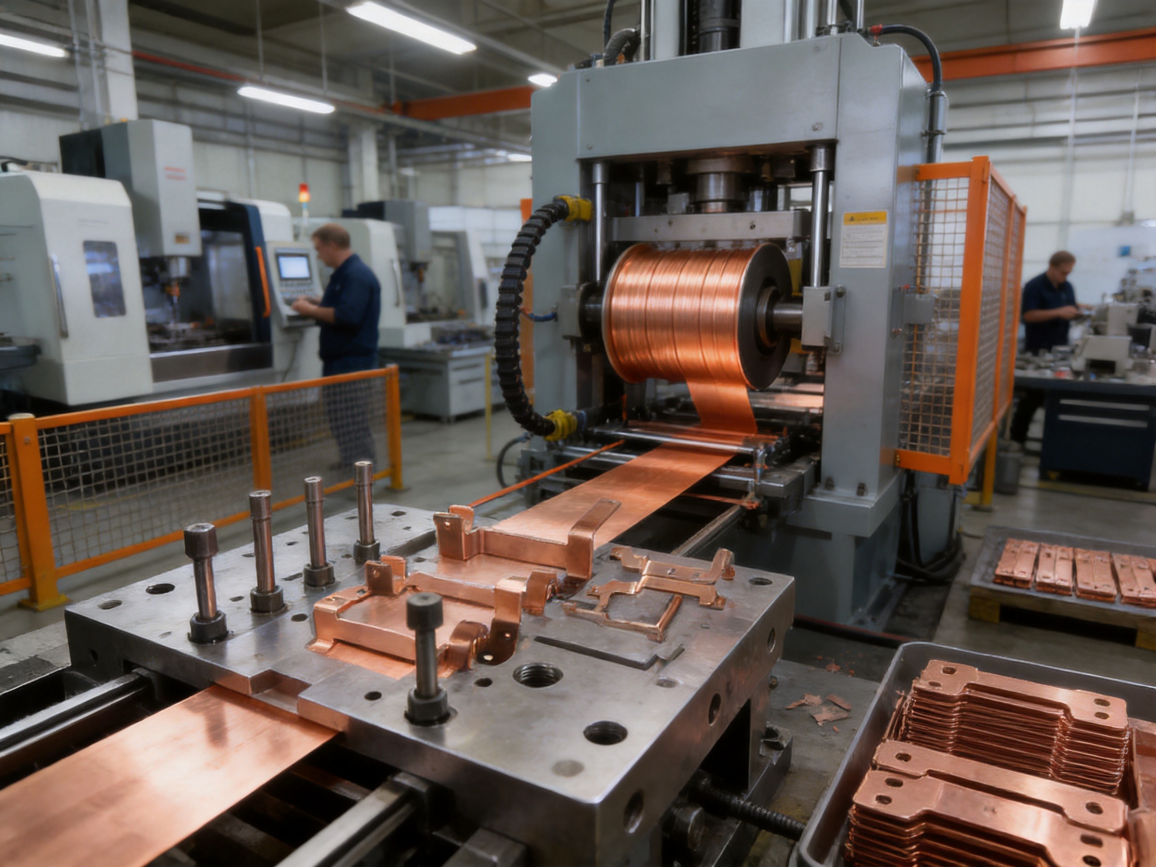
5.6 Stamping Production
Once the die has passed validation, production can be carried out on an appropriate punch press. The available press range of approximately 80 to 400 tons supports a broad range of stamping applications. The required press capacity depends on material thickness, perimeter length, number of operations, forming force, die design, and safety margin.
Press settings such as stroke, speed, feed pitch, shut height, lubrication, and material alignment must be controlled. Copper stamping may require special attention to galling, surface marking, tool wear, and material adhesion. Proper lubrication and suitable tool-surface treatment can help maintain stable production.
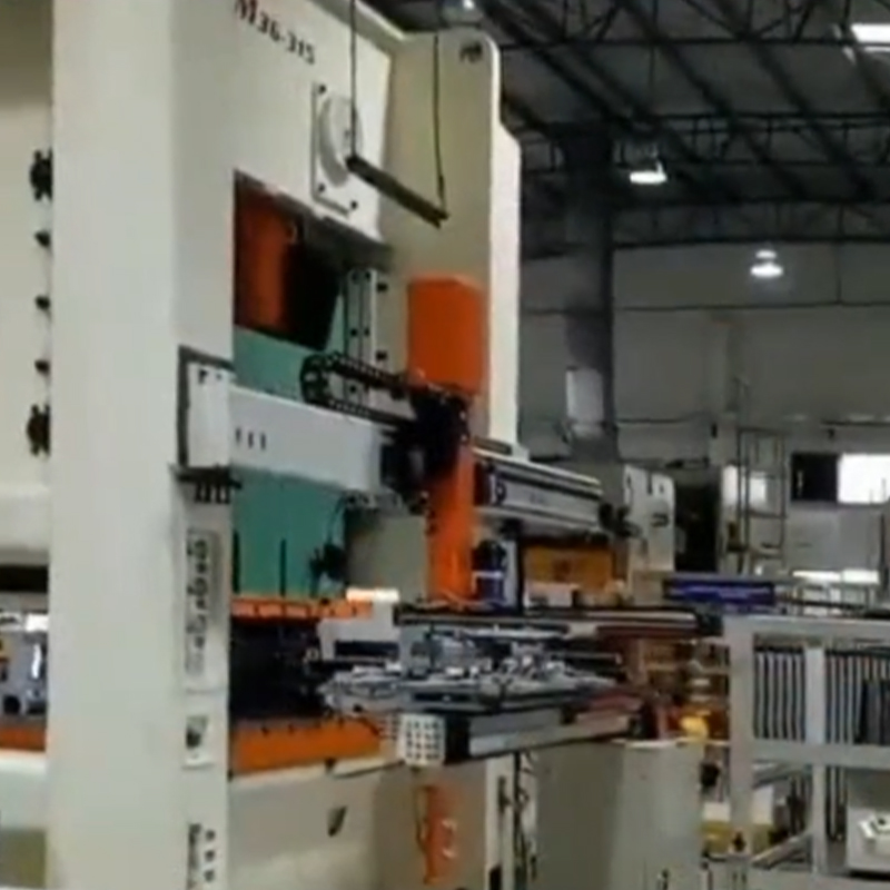
For large-volume programs, automation equipment can feed the strip, transfer parts, separate scrap, detect faults, and collect finished components. Automation improves output consistency and reduces direct manual contact with delicate copper surfaces.
6. Manufacturing Equipment and Technical Capabilities
The company’s manufacturing resources include imported wire cutting machines, CNC machining centers, more than ten grinding machines of different sizes, and approximately twenty-five punch presses ranging from 80 to 400 tons. This combination of equipment supports the complete development path from die component machining to stamped-part production.
Wire cutting equipment enables accurate machining of hardened or difficult-to-machine die components and is especially valuable for intricate profiles, narrow slots, and precision cutting edges. CNC machining centers support efficient production of die bases, plates, inserts, forming blocks, and other components requiring multiple coordinated surfaces.
Grinding equipment provides the dimensional refinement necessary for die alignment and working-surface quality. Different machine sizes allow the production team to select equipment according to the dimensions and tolerance requirements of each tool component.
The range of punch presses allows production planning to match part requirements with suitable press capacity. Smaller parts and lower-force operations can be allocated to appropriate machines, while larger or more demanding forming operations can use higher-capacity equipment.
Equipment alone does not guarantee quality. The company also has experienced toolmakers, senior press operators, debugging personnel, and technical staff who understand the relationship between die construction, press behavior, material characteristics, and finished-part performance. This combination of equipment and practical experience is particularly important for copper busbars, where small changes in clearance, support, or forming sequence can affect the result.
7. Quality Control for Automotive Copper Busbars
7.1 Incoming Material Inspection
Incoming copper material should be verified before it enters production. The inspection process may include checking material certificates, grade, thickness, width, hardness, surface condition, and coil or sheet identification. Traceability records help connect raw material batches with production orders and inspection results.
Material variation can affect stamping force, springback, edge quality, and forming behavior. Controlling the material at the beginning of the process therefore helps reduce later adjustments and production interruptions.
7.2 In-Process Inspection
In-process inspection can be performed at defined intervals or through continuous monitoring. Operators and quality personnel may inspect hole dimensions, external profile, bend angle, flatness, burr height, surface condition, and critical reference dimensions.
For automated lines, sensors can detect missing material, feeding errors, double hits, part presence, or abnormal conditions. Automatic shutoff functions can help prevent large quantities of nonconforming parts when a process deviation occurs.
7.3 Final Inspection
Final inspection confirms that finished busbars meet drawing and customer requirements. Depending on the product, inspections may include dimensional measurement, visual examination, plating thickness verification, burr inspection, flatness measurement, and assembly checks using customer-approved fixtures.
Electrical tests may be specified by the customer or system integrator. These can include resistance testing, insulation-related checks after overmolding or coating, contact-interface evaluation, and high-current thermal testing. The exact test plan should reflect the final application and applicable automotive requirements.
7.4 Reliability Considerations
New energy vehicle components may experience vibration, temperature changes, humidity, chemical exposure, and repeated current cycling. The busbar design and production process should therefore be evaluated for mechanical and environmental reliability.
The stated operating range for these busbar parts can extend from approximately -40 degrees Celsius to 125 degrees Celsius, depending on the material, coating, insulation, and application. Validation may include thermal cycling, vibration testing, corrosion testing, current-carrying tests, fastening tests, and dimensional checks after environmental exposure.
A reliable busbar must maintain both its electrical and mechanical functions. A part that remains electrically conductive but develops a crack, loosens at a fastening point, or loses alignment may still create a serious system problem. Quality control therefore needs to cover the complete component function rather than only its appearance.
8. Surface Plating, Insulation, and Assembly Integration
Some copper busbars are used as bare conductive parts inside protected housings. Others receive plating, insulating coatings, sleeves, films, overmolding, or additional protective structures. The selected solution depends on the required voltage rating, clearance, creepage distance, environmental exposure, and assembly design.
Plating specifications should identify the treated surface, base material, coating material, minimum thickness, adhesion requirements, appearance, and test method. Selective plating may be used when only the contact zones require protection, helping control cost while preserving the required electrical performance.
Insulation can be applied to prevent accidental contact and maintain separation between adjacent conductors. The busbar geometry should be designed with insulation thickness, wrapping radius, edge protection, and assembly tolerances in mind. Sharp corners and excessive burrs can damage insulating materials during installation or vibration.
Integration with terminals and fasteners is another important consideration. Hole diameter, countersink requirements, bolt clearance, washer size, contact pressure, and torque conditions all influence connection reliability. A stamped busbar should provide sufficient contact area and mechanical support without creating local deformation around the fastener.
When busbars are assembled with battery cells or modules, the design may include fusible sections, sensing tabs, laser-welding areas, ultrasonic-welding areas, or connection points for monitoring circuits. Each added feature must be evaluated for its effect on stamping, heat treatment, coating, and final assembly.
9. Current-Carrying Capacity and Thermal Performance
The product range can support current-carrying requirements from approximately 30 to 2,000 amperes, depending on the cross section, copper grade, cooling environment, duty cycle, and system design. This range covers many applications, from auxiliary power distribution and battery monitoring connections to high-current propulsion and charging circuits.
Current capacity is determined by more than nominal amperage. Continuous current, peak current, pulse duration, ambient temperature, installation orientation, adjacent conductors, cooling conditions, and allowable temperature rise must all be considered. The busbar should be evaluated together with its terminals, fasteners, coatings, insulation, and enclosure.
Copper’s low electrical resistivity helps reduce I²R losses, where heat generation increases with the square of current. This relationship means that reducing resistance can have a meaningful effect in high-current systems. A carefully designed busbar can therefore contribute to improved efficiency and reduced thermal stress.
Thermal expansion must also be considered. Copper expands and contracts with temperature changes, and differences in expansion between copper, aluminum, steel, plastics, and ceramics may create stress at mounting points. Flexible sections, controlled bend geometry, slotted mounting holes, or compliant connection designs may be used where necessary.
Engineering validation should confirm that the busbar remains within the intended temperature range during continuous and peak operating conditions. Thermal imaging, thermocouple measurement, resistance testing, and accelerated current cycling can provide useful data for design verification.
10. Why Integrated Die and Automation Support Matters
A major advantage of working with a supplier that provides both stamping dies and automation equipment is the ability to coordinate the tooling and production system from the beginning. The die must operate correctly within the intended press and automation environment. Feed height, strip width, transfer motion, part discharge, sensor positions, and maintenance access all affect line performance.
Separate suppliers may design the die, press process, and automation system independently. This can create interface problems, additional commissioning time, and unclear responsibility when production issues occur. An integrated supplier can assess the complete process and optimize the relationships between the die, press, feeder, transfer system, inspection devices, and collection equipment.
Automation can also support consistent quality by reducing variation caused by manual handling. It can control feeding speed, part orientation, transfer timing, and finished-part separation. Automated inspection can be added for critical holes, missing features, incorrect bends, or visible defects.
The company established Suzhou Keshuang Intelligent Technology Co., Ltd. in 2016 to focus on stamping automation equipment. This provides an additional capability for customers seeking turnkey solutions that combine stamping molds, production equipment, and automation. In some projects, the company can also invest in related production equipment according to customer requirements, helping provide a more cost-effective implementation route.
For a new energy vehicle busbar program, integrated support can reduce the gap between prototype development and mass production. The supplier can help define the tooling concept, process sequence, automation level, inspection approach, production capacity, and maintenance requirements as one connected plan.
11. Company Manufacturing Strengths
Suzhou Shuangqisi Mold Equipment Co., Ltd. is located in the Wujiang Economic Development Zone of Suzhou, China. The company specializes in stamping dies and hardware parts and combines design, manufacturing, production support, and service.
With approximately 60 technical staff and around 15 years of experience in the mold industry, the company has developed capabilities in die construction, stamping process debugging, precision machining, and customer-specific manufacturing. Its technical team supports applications for servo drives, compressors, electrical products, and new energy vehicles.
The company’s customer base includes Anter Group, Ousheng Electric, Dongbei Group, and Huichuan Technology. These customers are associated with industrial and new energy applications that require dependable molds and stamped products.
Its production equipment includes imported wire cutting machines, CNC machining centers, more than ten grinding machines, and approximately twenty-five punch presses with capacities from 80 to 400 tons. This equipment base supports both tooling manufacture and production stamping.
Experienced senior operators and debugging personnel provide practical support during die tryout and production ramp-up. Their experience helps identify issues such as uneven feeding, material deformation, springback, excessive burrs, tool wear, and production instability.
The company emphasizes integrated mold-making and stamping automation, reliable technical expertise, strict cost and quality control, and the development of long-term customer value. For customers purchasing new energy vehicle copper busbar stamping parts, this combination can simplify supplier management and improve coordination between product development, tooling, and production.
12. Design Recommendations for Better Busbar Production
12.1 Use Practical Bend Radii
Bend radii should be selected according to copper grade, thickness, temper, and forming direction. A radius that is too small may create cracks, surface damage, or reduced mechanical strength. A practical radius allows the material to form smoothly and provides a more stable tool life.
12.2 Maintain Adequate Edge Distance
Holes and slots placed too close to an edge or bend line may cause distortion, tearing, or insufficient strength. Maintaining adequate edge distance improves stamping stability and supports reliable fastening. If packaging constraints make a small edge distance unavoidable, the tool may require local forming support or a special operation sequence.
12.3 Consider Springback During Tool Design
Copper can spring back after bending, especially when the part is thin, wide, or formed across a long section. The die may need over-bending, coining, restriking, or a dedicated calibration operation to achieve the final angle. Springback compensation should be confirmed during tryout rather than estimated only from a theoretical model.
12.4 Avoid Unnecessary Geometry
Every additional bend, notch, tab, and hole increases die complexity and may affect material utilization. A simplified design can reduce tooling cost, improve production speed, and make inspection easier. At the same time, features that support assembly, electrical safety, and positioning should be retained when they provide clear functional value.
12.5 Define Functional Tolerances
Not every dimension requires the same tolerance. Critical features such as contact holes, mounting references, terminal positions, and mating edges should receive appropriate controls. Less critical dimensions can use practical tolerances to avoid unnecessary manufacturing cost.
12.6 Plan for Plating and Insulation
Plating and insulation should be considered before finalizing the stamped geometry. Coating thickness, masking areas, bend deformation, contact surfaces, and edge condition may affect the final dimensions. Early coordination between the stamping supplier and finishing supplier helps prevent fit problems.
13. Applications in Electric and Hybrid Vehicles
New energy vehicle copper busbar stamping parts can be used in high-voltage battery packs, where they connect cell groups, modules, contactors, current sensors, fuses, and external terminals. Their compact shape allows conductive paths to be positioned within protective battery structures.
They are also suitable for power distribution units that route current between the battery, inverter, onboard charger, DC/DC converter, and auxiliary systems. In these assemblies, busbars can reduce wiring complexity and provide defined connection points for service and inspection.
Inverters and motor control systems may require busbars capable of handling high current and rapid switching conditions. The geometry must support electrical performance while remaining compatible with insulation, cooling, and vibration requirements.
Charging systems, energy storage equipment, battery swapping systems, and stationary power modules can use similar copper busbar technologies. Although the vehicle environment is particularly demanding, many design and manufacturing principles apply to industrial energy storage and power conversion equipment.
14. Cost and Lifecycle Benefits
The initial tooling investment for a stamped busbar may be higher than the cost of making a small number of manually fabricated prototypes. However, for production programs, stamping can provide lower unit cost through high output, repeatable cycles, reduced labor, and efficient material handling.
Integrated features can also reduce the number of purchased components. A single stamped busbar may replace a cable, two terminals, a mounting bracket, and several manual operations. This can simplify purchasing, inventory, assembly, and quality documentation.
Reliable dimensional control may reduce field issues associated with loose connections, incorrect routing, inconsistent bend locations, or interference with surrounding components. Lower electrical resistance and improved thermal behavior may also contribute to system efficiency over the vehicle lifecycle.
Tool maintenance is an important part of lifecycle cost. A well-designed die with replaceable inserts, accessible wear components, suitable materials, and clear maintenance procedures can support long-term production. Preventive maintenance helps control burr growth, dimensional drift, and unexpected downtime.
15. Project Development and Customer Cooperation
A successful busbar project normally begins with the exchange of technical information. The customer should provide part drawings or three-dimensional models, copper grade, thickness, surface treatment, annual demand, packaging information, electrical requirements, inspection standards, and any applicable automotive quality requirements.
The supplier can then review feasibility, recommend a die concept, estimate material utilization, select a press capacity, propose an automation level, and identify potential risks. For complex parts, prototype or soft-tool production may be used to verify the design before final high-volume tooling is completed.
During tool development, design reviews should address critical dimensions, datum systems, inspection methods, strip layout, forming sequence, maintenance access, spare parts, and production capacity. Clear communication at this stage reduces the risk of misunderstanding and late design changes.
Before mass production, samples should be evaluated for dimensional compliance, appearance, assembly fit, electrical performance, plating quality, and environmental reliability where applicable. A production validation plan can define the acceptance criteria and documentation required for release.
After production begins, regular feedback supports continuous improvement. Tool wear, material changes, design updates, and changes in annual demand may require process adjustments. A supplier with both tooling and production capabilities can respond more efficiently because it understands the complete manufacturing history of the part.
16. Comparison of Copper Busbar Manufacturing Approaches
| Manufacturing Approach | Main Strength | Typical Limitation | Suitability for High-Volume EV Programs |
|---|---|---|---|
| Manual cutting and bending | Fast for simple prototypes and low quantities | Higher labor content and greater dimensional variation | Limited |
| CNC machining | Flexible for complex prototypes and small batches | Longer cycle time and more material waste for thin flat parts | Moderate for prototypes |
| Laser cutting and separate forming | Flexible profile development and short setup time | May require multiple operations and additional edge treatment | Moderate |
| Progressive stamping | High repeatability, efficient cycles, and integrated operations | Requires dedicated tooling investment | Excellent |
| Transfer stamping | Suitable for complex three-dimensional forming | Higher system complexity and tooling cost | Excellent for complex parts |
| Integrated stamping automation | Reduced manual handling and coordinated production control | Requires careful system planning and commissioning | Excellent for stable mass production |
The most suitable approach depends on production volume, geometry, tolerance, material thickness, and development stage. Prototypes may benefit from flexible machining or laser processing, while mature vehicle programs generally benefit from dedicated stamping tools and automated production.
17. Environmental and Compliance Considerations
New energy vehicle suppliers increasingly need to control material declarations, restricted substances, traceability, and process documentation. The product information provided for these copper busbar stamping parts identifies RoHS compliance as part of the intended specification, together with automotive-oriented quality expectations such as IATF 16949 and ISO standards.
Compliance should be confirmed according to the specific project, material, plating supplier, and customer audit requirements. Plating chemicals, cleaning agents, lubricants, packaging materials, and protective coatings may all require documentation and controlled handling.
Material efficiency is another important consideration. Strip-layout optimization can reduce copper scrap, especially because copper has a higher material value than many common stamping metals. Scrap should be collected and recycled through controlled channels where possible.
Automation and stable process control can also reduce rework, rejected parts, and unnecessary energy consumption. A robust die design supports longer tool life, fewer interruptions, and more predictable production performance.
18. Frequently Asked Questions
Q1: What are new energy vehicle copper busbar stamping parts?
They are precision-formed copper conductive components used to distribute high-voltage or high-current power in electric vehicles, hybrid vehicles, battery packs, inverters, charging systems, and related electrical assemblies. They are produced through stamping operations such as blanking, piercing, bending, forming, and coining.
Q2: Which copper materials can be used?
Common choices include C11000, C10100, and T2 copper. The final selection depends on conductivity, purity, hardness, thickness, forming performance, surface treatment, and customer requirements. High-purity copper with approximately 99.9 percent or higher copper content can provide strong electrical performance.
Q3: What current range can these busbars support?
The described product range can support approximately 30 to 2,000 amperes. Actual current capacity depends on cross-sectional area, copper grade, ambient temperature, cooling conditions, duty cycle, allowable temperature rise, and the complete electrical assembly.
Q4: Why use a busbar instead of a wiring harness?
A busbar can offer lower resistance, improved heat dissipation, more compact packaging, fewer connection points, better positional repeatability, and more efficient high-volume assembly. A wiring harness may still be preferable for flexible routing or certain low-current circuits, so the choice should be based on the system design.
Q5: What surface treatments are available?
Tin, nickel, and silver plating are possible options. Coating thickness may be approximately 3 to 5 micrometers, depending on the application and specification. Surface treatment improves corrosion resistance and can stabilize contact performance.
Q6: Can complex three-dimensional busbars be stamped?
Yes. Depending on the geometry, progressive, transfer, compound, or multi-stage forming can be used. Complex designs may require several controlled bending and calibration operations to manage springback, avoid cracking, and maintain alignment.
Q7: What dimensional accuracy is possible?
Precision stamping can achieve dimensional accuracy within approximately ±0.05 to ±0.2 millimeters for selected features, depending on material thickness, part geometry, tolerance location, die structure, and inspection method. Critical dimensions should be reviewed during the feasibility stage.
Q8: How is burr quality controlled?
Burr control depends on punch-to-die clearance, tool sharpness, die alignment, material condition, cutting direction, and maintenance. Additional deburring or edge treatment may be included if the part requires enhanced insulation safety, assembly protection, or strict edge specifications.
Q9: What press capacities are available?
The company operates approximately twenty-five punch presses ranging from 80 to 400 tons. The appropriate press is selected according to material thickness, part size, forming force, die design, production speed, and safety requirements.
Q10: Can the supplier provide automation as well as stamping dies?
Yes. The company has integrated mold-making and stamping automation capabilities. Its related automation business focuses on stamping automation equipment and can support feeding, transfer, inspection, collection, and other production functions according to the project requirements.
Q11: What information should a customer provide for a quotation?
Useful information includes part drawings or three-dimensional data, material grade, thickness, surface treatment, annual volume, prototype requirements, dimensional tolerances, electrical requirements, packaging details, inspection standards, and the expected production schedule.
Q12: Are these busbars suitable for high-temperature and vibration environments?
They are designed for demanding automotive conditions and can withstand vibration and temperature extremes from approximately -40 to 125 degrees Celsius, subject to the specific material, coating, insulation, fastening system, and validation requirements of the final application.
19. Conclusion
New energy vehicle copper busbar stamping parts provide a practical and efficient solution for high-voltage power distribution. High-purity copper delivers excellent electrical and thermal conductivity, while precision stamping creates repeatable geometries that support compact packaging, reliable assembly, and large-scale production.
Compared with conventional wiring assemblies or manually fabricated copper components, stamped busbars can reduce resistance, heat generation, assembly complexity, space consumption, and part variation. Proper material selection, die design, forming sequence, plating, inspection, and automation are all necessary to achieve these advantages consistently.
Suzhou Shuangqisi Mold Equipment Co., Ltd. combines stamping die design and manufacturing with stamped-part production and automation equipment. Its wire cutting machines, CNC machining centers, grinding equipment, punch presses, technical staff, senior operators, and debugging personnel support a complete manufacturing process from engineering review to production delivery.
For electric vehicle manufacturers, battery-system integrators, power-electronics producers, and industrial energy companies, this integrated capability can simplify project coordination and support cost-effective production. By selecting the correct copper material, optimizing the busbar geometry, controlling the die process, and applying appropriate surface protection, customers can develop conductive components that meet the electrical, mechanical, thermal, and manufacturing demands of modern electrified systems.
References
1. Automotive Industry Action Group. Quality Management System Requirements for Automotive Production and Relevant Service Parts.
2. International Organization for Standardization. ISO 9001 Quality Management Systems—Requirements.
3. International Automotive Task Force. IATF 16949 Quality Management System Requirements for Automotive Production and Relevant Service Parts Organizations.
4. European Parliament and Council. Restriction of Hazardous Substances Requirements for Electrical and Electronic Equipment.
5. Copper Development Association. Copper Electrical Conductivity, Thermal Performance, and Busbar Engineering Principles.
6. ASM International. Metal Forming Fundamentals and Sheet Metal Stamping Process Guidance.
7. Society of Automotive Engineers. Recommended Practices for High-Voltage Electrical Systems in Electrified Vehicles.
8. International Electrotechnical Commission. General Principles for Electrical Clearances, Creepage Distances, and Insulation Coordination.
9. Manufacturer technical information for C11000, C10100, and T2 high-conductivity copper materials.
10. Manufacturer process documentation for precision stamping dies, copper busbar forming, plating, inspection, and stamping automation equipment.
Product: New energy vehicle copper busbar stamping parts
Previous Post
Battery Cover Stamping Parts: Precision Protection for Next-Generation Battery Systems
Next Post
Progressive Molds for Automotive Parts: Precision, Productivity, and Integrated Stamping Solutions
Our Products.
Start Your Business with an OEM Manufacturer Right Here!

Provide global customers with complete turn-key solutions
through
innovation!
QUICK LINKS
CONTACT INFO.
-
 +86-139 1308 8972
 -

-
 No. 118 Yexin Road, Wujiang Economic Development Zone, Suzhou, China
Copyright © Suzhou Shuangqisi Mold Equipment Co., Ltd. All Rights Reserved. Custom Stamping Die Metal Stamping Die Manufacturers
