 English
 Español
 Deutsch
-
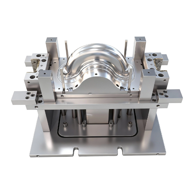
Deep drawing mold for front and rear wheels of two-wheeled electric vehicles
This Deep drawing mold for front and rear wheels o...
-
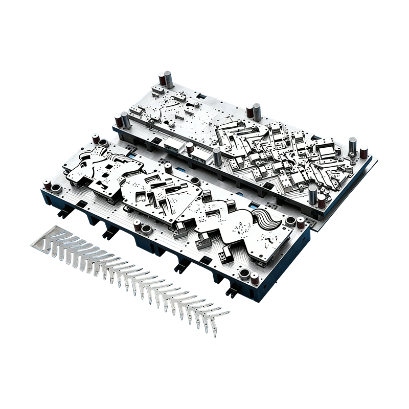
Progressive molds for automotive parts
This Continuous mold for automotive motor housing ...
-
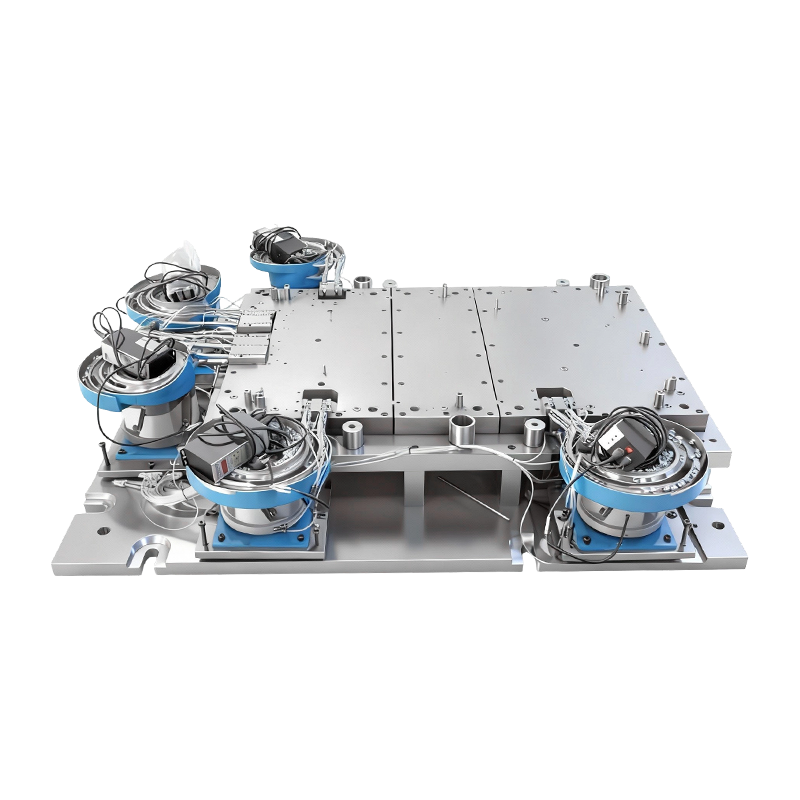
Automatic riveting mold for large computer machine base
This Automatic Riveting Mold for Large Computer Ma...
-
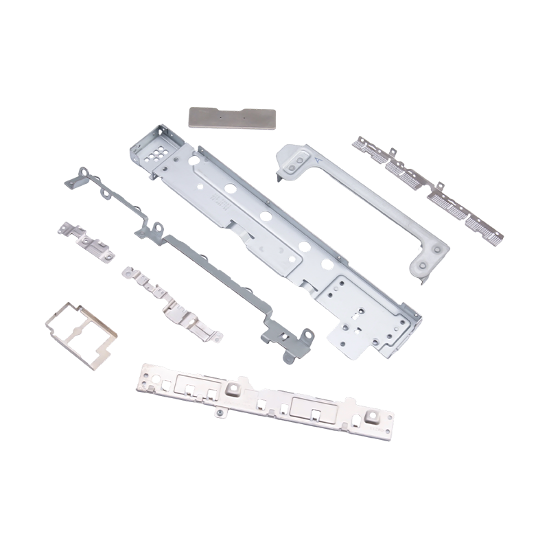
Small stamped parts for laptops and mobile phones
As essential internal components for modern portab...
-
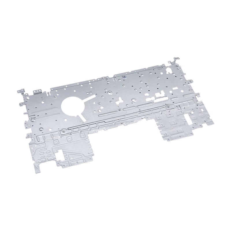
Laptop stamping parts
Our laptop stamping parts are precision-manufactur...
- E-mail us: [email protected]
- Call us: +86-139 1308 8972

Chen Siyi – Overseas Sales Manager
Home / Author / Chen Siyi – Overseas Sales Manager / Advanced Stamping Automation Equipment for Reliable, Efficient Metal Forming
Advanced Stamping Automation Equipment for Reliable, Efficient Metal Forming
2026-08-05
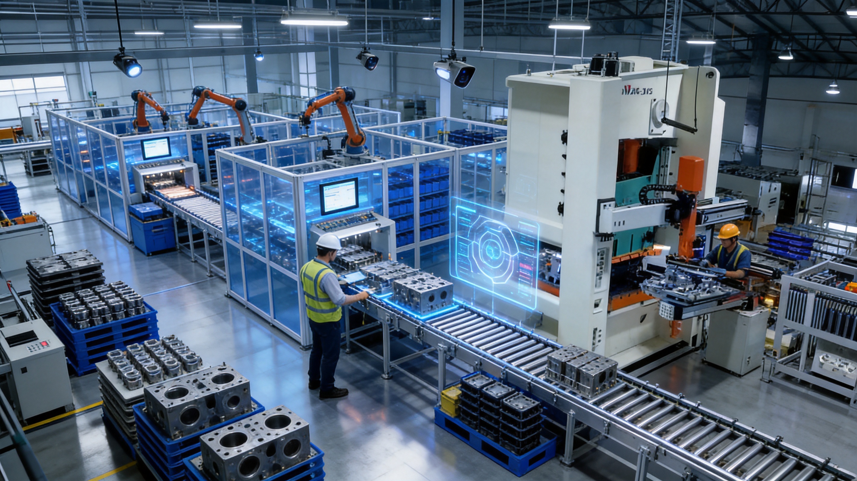
Stamping automation equipment has become an essential part of modern metal forming. As manufacturers face growing pressure to improve productivity, reduce operating costs, maintain consistent quality, and respond quickly to changing customer requirements, automated stamping systems provide a practical foundation for competitive production. Properly designed automation can coordinate material feeding, die operations, part transfer, inspection, collection, and production monitoring in one controlled process.
Suzhou Shuangqisi Mold Equipment Co., Ltd. provides stamping automation equipment as part of an integrated manufacturing capability that also includes stamping die design, die manufacturing, hardware part production, debugging, and technical service. This combination allows the company to approach automation from the perspective of the entire stamping process rather than treating the automation unit as an isolated machine. The result is a more coordinated solution for customers requiring stable production, efficient material handling, and dependable integration with stamping dies and presses.
The company’s product and service capabilities are supported by approximately 15 years of experience in the mold industry, a technical team of 60 employees, precision machining resources, grinding equipment, imported wire cutting machines, CNC machining centers, and a press capacity ranging from 80 tons to 400 tons. In addition, the company has invested in Suzhou Keshuang Intelligent Technology Co., Ltd., which focuses mainly on stamping automation equipment. This structure supports the development of integrated solutions for stamping molds and automated production lines.
For manufacturers of servo drives, compressors, new energy vehicle components, electrical products, and other precision hardware parts, the value of automation depends on more than speed alone. A successful system must match the press, die, material, part geometry, production volume, and quality requirements. It must also be easy to debug, maintain, and adapt. The following discussion explains how stamping automation equipment works, why integrated design is important, and how advanced manufacturing processes can help customers achieve more stable and cost-effective production.
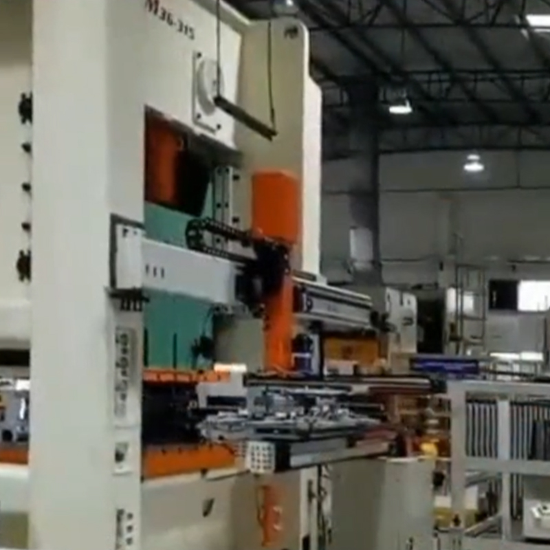
Stamping Automation Equipment
Content
- 1 Understanding Stamping Automation Equipment
- 2 Why Automation Is Important in Modern Stamping Production
- 3 Integrated Die and Automation Engineering
- 4 Core Types of Stamping Automation Equipment
- 5 Advanced Manufacturing Resources and Technical Strengths
- 6 Manufacturing Process for Stamping Automation Equipment
- 6.1 1. Application Review and Requirement Definition
- 6.2 2. Process and Layout Planning
- 6.3 3. Mechanical and Electrical Design
- 6.4 4. Component Machining and Fabrication
- 6.5 5. Assembly and Alignment
- 6.6 6. Electrical Installation and Programming
- 6.7 7. Trial Running and Debugging
- 6.8 8. Delivery, Installation, and Technical Support
- 7 Competitive Advantages of an Integrated Supplier
- 8 Applications Across Industrial Manufacturing
- 9 Quality Management in Automated Stamping
- 10 Energy, Efficiency, and Total Operating Cost
- 11 How to Select Suitable Stamping Automation Equipment
- 12 Turnkey Solutions for Stamping Production
- 13 Maintenance and Long-Term Reliability
- 14 Future Development of Stamping Automation
- 15 Questions and Answers
- 15.1 What is stamping automation equipment?
- 15.2 What types of products can use stamping automation?
- 15.3 Why is integrated die and automation design valuable?
- 15.4 Can automation equipment work with an existing stamping press?
- 15.5 Does automation eliminate the need for operators?
- 15.6 How does automation help reduce stamping defects?
- 15.7 What manufacturing capabilities support the equipment?
- 15.8 What is the benefit of a turnkey stamping solution?
- 15.9 How should stamping automation equipment be maintained?
- 15.10 What should customers provide when requesting a quotation?
- 16 Conclusion
- 17 References
- 18 Product: Stamping Automation Equipment
Understanding Stamping Automation Equipment
Stamping automation equipment is a group of mechanical, electrical, and control systems used to automate one or more stages of a metal stamping operation. Depending on the production process, the equipment may include coil feeding systems, straighteners, servo feeders, transfer mechanisms, robotic arms, material positioning units, unloading systems, part collection devices, safety systems, and production monitoring controls.
In a manual stamping process, operators may load blanks, move parts between operations, remove finished components, and inspect products by hand. This approach can be suitable for low-volume work or simple operations, but it usually creates limitations when production volume increases. Manual handling can introduce variation in part positioning, restrict press utilization, increase labor requirements, and expose workers to repetitive or hazardous tasks.
Automation addresses these limitations by controlling the movement and timing of materials and parts. A feeder can deliver strip material to the die with controlled accuracy. A transfer system can move formed parts from one station to another. A robotic unit can load blanks into a press and remove finished components. Sensors and control systems can detect missing material, incorrect positioning, or abnormal conditions before they cause extensive production problems.
The exact configuration depends on the product and process. A progressive die may require a high-precision coil feeder and straightener. A multi-operation forming process may require transfer automation between several die stations. A larger component may need a robotic loading and unloading system. A compact electrical component may require a fast, accurately synchronized feeding and collection solution.
Therefore, stamping automation equipment should not be selected by nominal speed alone. The correct system is determined by the relationship between the die, press, material, part geometry, stroke rate, required tolerances, production volume, and factory layout. An experienced equipment supplier must understand these relationships before recommending a configuration.
Why Automation Is Important in Modern Stamping Production
Higher and More Consistent Productivity
One of the clearest advantages of automation is the ability to maintain a repeatable production rhythm. Automated feeding and transfer reduce interruptions between operations and make better use of press capacity. When the press, die, feeder, and transfer system are properly synchronized, production can continue with fewer pauses caused by manual loading, unloading, or repositioning.
Consistency is especially important for customers producing large quantities of similar parts. A manual process may depend heavily on operator experience and attention. An automated process follows programmed motion sequences and controlled timing. This helps reduce variation from one cycle to the next and supports more predictable output.
Automation also improves production planning. When cycle times are stable, manufacturers can estimate capacity more accurately, schedule materials and labor more effectively, and provide more reliable delivery information to customers.
Improved Dimensional Stability
Many stamped components require controlled dimensions, precise hole locations, accurate forming angles, or consistent flatness. Part positioning is a critical factor in achieving these requirements. If a blank is placed inaccurately or a formed part is transferred with excessive movement, the resulting product may not meet specification.
Automated feeders, grippers, and transfer mechanisms can be designed to position material and parts repeatedly within the required process range. When combined with a properly manufactured die and an appropriate press, this improves the stability of the finished component. It also reduces the risk of defects caused by inconsistent manual handling.
Lower Labor Dependence
Automation does not eliminate the need for skilled personnel. Instead, it changes the role of employees from repetitive material handling to setup, process supervision, maintenance, quality control, and improvement activities. This can help manufacturers use technical staff more effectively while reducing the physical burden associated with repetitive press operations.
For factories facing labor shortages or rising labor costs, automated stamping can provide a more sustainable production model. A single operator may be able to supervise multiple automated processes, depending on the system design, safety requirements, product type, and level of integration.
Enhanced Workplace Safety
Press operations involve moving tools, high forces, sharp edges, and rapid mechanical actions. Reducing the need for operators to place or remove parts directly from the die area can lower exposure to common handling risks. Automated systems can incorporate guards, interlocks, emergency stop devices, sensors, and defined access procedures.
Safety must be considered from the beginning of the project. A system that is fast but difficult to access, inspect, or maintain may create unnecessary risks. Good automation design combines productivity with safe operating procedures, clear controls, and appropriate protection around moving components.
Reduced Material and Process Waste
Stable feeding and accurate positioning can help reduce scrap caused by misfeeds, incorrect alignment, double loading, and transfer errors. When a stamping process is integrated with the die and press from the design stage, material movement can be reviewed together with strip layout, forming sequence, and part removal.
Lower scrap improves material utilization and reduces the cost of handling defective parts. It also supports more responsible use of metals, energy, and production time. The exact level of improvement depends on the product, material, die design, operating conditions, and control strategy, but automation creates the foundation for more consistent process control.
Integrated Die and Automation Engineering
A major advantage of working with a supplier that can design and manufacture both stamping dies and automation equipment is the ability to coordinate the complete production system. The die determines how the material is cut, formed, pierced, bent, or drawn. The automation system determines how the material enters the die, how parts move, and how products leave the process. These functions must work together.
If the die and automation are developed separately, problems may appear during installation. The feeder may not provide sufficient clearance. The transfer fingers may interfere with the tool. The part may be difficult to grip after forming. The press stroke may not match the transfer timing. A die that functions correctly in manual operation may require modifications before it can operate reliably in an automated line.
Integrated engineering reduces these risks by reviewing the complete process before manufacturing begins. Important factors include:
Material type, thickness, width, and surface condition.
Blank shape, strip layout, pitch, and carrier design.
Number of forming, piercing, bending, and blanking operations.
Press tonnage, stroke, shut height, slide speed, and bolster dimensions.
Required production rate and cycle time.
Part geometry, weight, rigidity, and gripping surfaces.
Transfer distance, orientation, and clearance between stations.
Part collection, stacking, sorting, and packaging requirements.
Inspection points and abnormal-condition detection.
Factory space, operator access, maintenance areas, and material flow.
When these details are considered together, the automation system can be designed around the real process instead of being added after the die is already complete. This integrated approach is particularly valuable for complex components and high-volume applications where small process problems can generate significant production losses.
Core Types of Stamping Automation Equipment
Coil Feeding Systems
Coil feeding systems supply strip material to a stamping press at a controlled rate. A typical system may include a decoiler, straightener, feeder, and control unit. The decoiler supports the material coil, the straightener removes curvature, and the feeder advances the strip into the die.
A reliable coil feeding system must maintain accurate pitch and coordinate movement with the press. Excessive tension, poor straightening, or inaccurate feed length can affect the position of holes, bends, and cut features. Servo-driven feeding provides programmable control and can support different material lengths, speeds, and production recipes.
The design must also consider coil weight, strip width, material thickness, line speed, and available factory space. For high-volume production, automatic monitoring of material position and coil status can reduce interruptions and help operators manage the line more effectively.
Servo Feeders and Straighteners
Servo feeders use controlled motor movement to advance material with repeatable accuracy. Compared with less flexible mechanical feeding methods, servo systems can offer easier adjustment of feed length, acceleration, deceleration, and production settings. They are suitable for applications requiring different part pitches or frequent product changes.
Straighteners are important because coiled material retains curvature after unwinding. If the strip enters the die with excessive curvature or twist, it may not lie correctly on the die surface. This can cause feeding errors, dimensional variation, or damage to the tool. A properly matched straightener improves the condition of the material before it reaches the forming area.
Transfer Systems
Transfer systems move parts between multiple die stations or between separate presses. They may use mechanical transfer bars, grippers, fingers, rails, or programmable servo axes. The system must maintain the correct part orientation while avoiding contact with the die, press, or neighboring components.
Transfer automation is particularly useful for processes involving several forming stages. Instead of requiring an operator to reposition the part at each step, the transfer system performs the movement at a coordinated speed. This supports continuous operation and can improve both output and repeatability.
Designers must analyze the part’s stiffness, weight, shape, and surface sensitivity. A gripping method that is appropriate for a rigid steel bracket may not be appropriate for a thin formed shell or a component with a cosmetic surface. The contact points, gripping force, release timing, and transfer path must all be considered.
Robotic Loading and Unloading
Robotic systems can load blanks into a press, remove finished products, transfer parts between processes, or place components into containers. Robots are useful when the workpiece is large, heavy, irregularly shaped, or difficult to transfer with a conventional mechanical system.
A robotic cell may include a material positioning table, part detection sensors, grippers, safety fencing, a press interface, and a programmable controller. The robot can be configured for different motion sequences and product models, making it suitable for flexible manufacturing environments.
Robotic loading and unloading can also help separate workers from high-temperature, sharp-edged, or oily parts. However, the system must be carefully programmed and validated. Collision prevention, tool identification, gripper confirmation, and safe recovery after an interruption are important parts of the design.
Part Collection and Sorting Systems
Once parts leave the die, they must be collected in a controlled way. Part collection equipment may include conveyors, chutes, bins, stacking devices, sorting mechanisms, or packaging interfaces. Correct collection prevents scratches, deformation, mixing of different part numbers, and unnecessary manual handling.
For components with different quality grades or production batches, automated sorting can help maintain traceability. Sensors or inspection stations may be used to identify missing features, incorrect orientation, or visible defects before parts are placed into final containers.
Control and Monitoring Systems
The control system coordinates the press, feeder, transfer equipment, sensors, and safety devices. It may manage production recipes, speed settings, alarms, fault recovery, and communication between machines. A clear operator interface makes it easier to select products, adjust settings, identify causes of stoppage, and resume production safely.
Monitoring functions can include feed position, press status, part presence, overload conditions, die protection, material shortage, transfer position, and emergency stop status. The more complex the line, the more important it becomes to organize alarms and diagnostic information in a practical way.
| Automation Module | Primary Function | Typical Benefit | Important Design Considerations |
|---|---|---|---|
| Decoiler | Supports and releases coil material | Continuous material supply | Coil weight, width, tension, and floor space |
| Straightener | Removes curvature from strip material | Improved material stability | Material thickness, hardness, and roll adjustment |
| Servo feeder | Advances strip material into the die | Accurate and programmable feeding | Feed length, speed, pitch, and press synchronization |
| Transfer system | Moves parts between die stations | Continuous multi-stage production | Part geometry, gripping points, clearance, and timing |
| Robotic unit | Loads, unloads, or transfers workpieces | Flexible handling and reduced manual exposure | Payload, reach, gripper design, safety, and programming |
| Part collection unit | Receives and organizes finished components | Reduced damage and improved material flow | Part orientation, stacking, packaging, and sorting |
| Control system | Coordinates machines and monitors conditions | Stable operation and easier troubleshooting | Interface design, sensors, alarms, and communication |
Advanced Manufacturing Resources and Technical Strengths
The performance of stamping automation equipment depends partly on the quality of the components used to build it. Frames, brackets, guide structures, transfer components, grippers, support plates, and precision interfaces must be manufactured accurately. Weak or poorly aligned components can create vibration, positioning errors, premature wear, and difficult maintenance.
The company’s manufacturing resources include imported wire cutting machines, CNC machining centers, more than 10 grinding machines of various sizes, and other precision machine tools. These resources support the production of stamping dies, automation components, fixtures, and related hardware parts.
Wire Cutting and Precision Profile Manufacturing
Wire cutting is valuable for producing complex profiles, narrow slots, precise openings, and hardened die components. In stamping die manufacturing, wire electrical discharge machining can produce features that are difficult to create with conventional cutting tools. It is also useful for manufacturing accurate inserts and components used in forming and guiding systems.
Precision wire cutting contributes to repeatability between mating components. Accurate profiles can improve die assembly, reduce adjustment time, and support more stable production during commissioning. In automation equipment, similar capabilities can be applied to brackets, positioning elements, guide components, and custom interfaces.
CNC Machining Centers
CNC machining centers support the production of die plates, bases, mounting structures, precision holders, and automation components. Computer-controlled machining allows complex surfaces and multiple features to be produced according to programmed specifications. This supports better dimensional control and reduces dependence on manual rework.
For integrated projects, CNC machining can help maintain consistency between the die, press interface, and automation structure. Mounting holes, reference surfaces, guide locations, and component clearances must often correspond accurately. Centralized machining capability can make these relationships easier to control.
Grinding Operations
Grinding is used where surface finish, flatness, parallelism, or tight dimensional control is important. The company operates more than 10 grinding machines of different sizes, supporting the preparation of die plates, inserts, guide components, and other precision parts.
Good grinding practice contributes to stable assembly. Flat and parallel surfaces help reduce unwanted movement and uneven loading. Accurate guide components support smooth motion and help protect both the die and automation equipment from excessive wear.
Press Capacity for Validation and Production
The company has 25 punch presses ranging from 80 tons to 400 tons. This range provides practical support for stamping trials, die debugging, sample production, and hardware part manufacturing across different product sizes and forming requirements.
Press capacity is not simply a matter of selecting a machine with sufficient nominal tonnage. The press must also match the die dimensions, stroke, shut height, speed, bolster arrangement, feeding direction, and production method. Having access to different press capacities helps make it possible to evaluate the tooling under more appropriate operating conditions.
Experienced Operators and Debugging Personnel
Automation equipment may be manufactured accurately and still require careful commissioning. The interaction between material, die, press, feeder, and transfer system can reveal issues that are not visible in drawings. Experienced operators and debugging personnel can adjust feeding timing, sensor positions, gripping force, die clearances, and operating parameters.
Practical debugging experience is especially important for products with several forming operations. Minor changes in material behavior or tool adjustment can affect the transfer path and the final part. A technical team that understands both mold performance and machine movement can identify problems more efficiently.
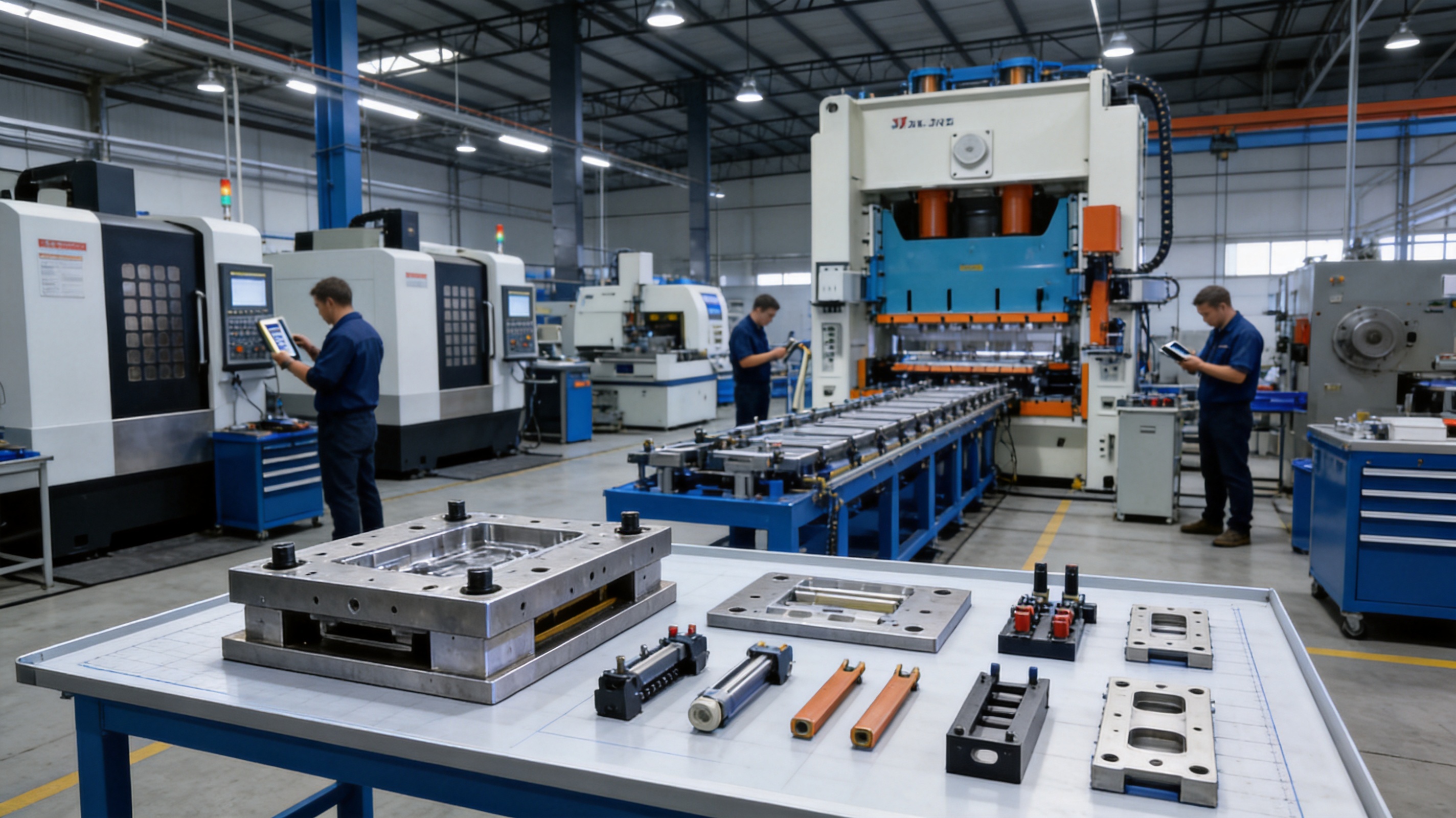
Manufacturing Process for Stamping Automation Equipment
1. Application Review and Requirement Definition
The process begins with an understanding of the customer’s product and production objectives. Engineers review part drawings, material data, required tolerance, expected output, press information, existing equipment, and factory conditions. If the project involves a new die, the stamping sequence and automation method can be considered together from the start.
At this stage, the supplier should identify critical questions. Is the material supplied from coil or as individual blanks? How many operations are required? Does the part need to change orientation? Are there sensitive surfaces that must not be contacted? What is the expected production volume? Are multiple part numbers expected to share the same line? What type of inspection or traceability is necessary?
Clear requirements reduce later changes and help ensure that the proposed system is appropriate for the customer’s actual operating environment.
2. Process and Layout Planning
After the requirements are defined, engineers develop the production concept. This may include the press arrangement, die stations, feeder location, transfer path, robot reach, material flow, operator access, maintenance space, and collection method.
Layout planning should consider both operation and service. A compact system may save floor space, but components still require access for inspection, lubrication, adjustment, and replacement. Material coils, finished containers, spare parts, and operator walkways must also be considered.
For integrated stamping projects, the strip layout and die sequence are reviewed together with automation movement. This helps prevent interference and allows the transfer system to be designed around real part positions.
3. Mechanical and Electrical Design
Mechanical design defines frames, supports, guides, transfer arms, grippers, feeders, guards, and interfaces. The structure must be sufficiently rigid to resist vibration and repeated dynamic loading. Moving components must have suitable clearances and controlled motion.
Electrical and control design defines motors, drives, sensors, programmable controllers, operator interfaces, safety circuits, and communication with the press. The control sequence must identify the correct order of events. For example, the feeder may need to confirm material position before the press begins a cycle, while the press may need to reach a safe position before a transfer movement starts.
Safety design should include emergency stops, access protection, interlocks, fault detection, and safe restart procedures. The system should make abnormal conditions visible to operators and prevent movement when a dangerous condition is detected.
4. Component Machining and Fabrication
Once the design is approved, components are produced using suitable machining and fabrication methods. CNC machining centers can manufacture structural and precision parts. Wire cutting can produce intricate profiles and tool components. Grinding can improve the accuracy and surface condition of mating parts.
Manufacturing plans should identify critical dimensions and reference surfaces. Components that affect part positioning or transfer timing require particular attention. Proper identification and inspection during production help prevent incorrect assembly later.
5. Assembly and Alignment
Assembly brings individual components together into a functional system. Guide rails, transfer elements, feeders, grippers, sensors, drives, guards, and control panels must be installed according to the approved design.
Alignment is a central concern. A small error in the relationship between the die, press, feeder, and transfer unit can become more significant during high-speed movement. Technicians check mechanical positions, motion ranges, clearances, fastener security, sensor locations, and interfaces with the customer’s press.
6. Electrical Installation and Programming
After mechanical assembly, the control system is wired and programmed. The program coordinates the automation sequence and monitors signals from sensors and safety devices. Product recipes may be created for different feed lengths, transfer positions, speeds, or operating modes.
Good programming should support both normal operation and fault recovery. Operators need clear instructions when a sensor detects a missing part, a feeder loses position, or an emergency stop is activated. A well-organized control structure can shorten troubleshooting time and reduce the risk of incorrect restart.
7. Trial Running and Debugging
Trial running begins at a controlled speed and progresses toward the intended operating conditions. Technicians observe material feeding, die entry, part formation, transfer movement, unloading, collection, and overall machine stability.
Adjustments may include feeder timing, servo acceleration, transfer position, gripper pressure, sensor sensitivity, die alignment, press speed, or part collection settings. The goal is not merely to make one successful cycle but to demonstrate repeatable operation over an appropriate trial period.
Samples from the trial can be inspected for dimensions, forming quality, burrs, cracks, scratches, deformation, and other customer requirements. If a defect is related to tool or handling behavior, the integrated engineering team can evaluate the cause and make appropriate corrections.
8. Delivery, Installation, and Technical Support
After internal testing, the equipment can be prepared for shipment and installation. Documentation may include operating instructions, maintenance recommendations, electrical information, spare parts information, and safety procedures.
Installation requires careful leveling, connection, alignment, and interface confirmation. Operators and maintenance personnel should receive practical training on startup, shutdown, product changeover, alarm response, lubrication, inspection, and safe access.
Technical support remains important after commissioning. Stamping conditions can change when customers introduce new materials, change production speeds, or modify product specifications. An experienced supplier can help evaluate these changes and recommend suitable adjustments or improvements.
Competitive Advantages of an Integrated Supplier
One Source for Dies, Parts, and Automation
Many customers prefer a supplier that can coordinate stamping dies, hardware parts, and automation equipment within one project. This reduces the number of technical interfaces and simplifies communication. Instead of asking separate suppliers to resolve compatibility issues, the customer can work with one team that understands the complete process.
This integrated structure is particularly useful for turnkey projects. The supplier can support die design, machine construction, sample production, debugging, and process optimization. It can also help the customer evaluate production equipment and develop a solution based on the intended output and budget.
Reduced Integration Risk
When the die and automation are developed by different organizations, responsibility for problems may be unclear. A feeding error may be caused by the feeder, the strip layout, the die guide, or the press interface. A transfer problem may be related to part shape, gripping points, or station spacing.
An integrated supplier can examine these relationships as one technical problem. This can reduce the risk of delays during installation and make corrective action more direct. It also encourages designers to consider maintenance, changeover, and production practicality before the equipment is built.
Cost Control Through Internal Capability
Internal machining, grinding, assembly, debugging, and press resources can improve control over project cost and schedule. Fewer external manufacturing steps may reduce coordination time and make it easier to respond to design changes.
Cost effectiveness does not mean selecting the least expensive components or reducing essential quality controls. It means balancing investment with production needs. A system should provide the required accuracy, output, safety, reliability, and maintainability without unnecessary complexity. The company’s stated focus on strict cost and quality control supports this balanced approach.
Practical Understanding of Customer Applications
The company’s customers include organizations associated with servo drives, compressors, and new energy vehicles, as well as other industrial applications. These fields often require stable and repeatable production of metal components with controlled dimensions and reliable performance.
Experience with such applications can help engineers understand the importance of burr control, hole location, forming accuracy, material consistency, surface protection, and production traceability. The exact requirements vary by component, but practical application knowledge improves the quality of technical discussions and solution planning.
Capability to Support Production Equipment Investment
In addition to manufacturing molds and automation systems, the company can invest in related production equipment according to customer needs. This creates an option for customers that want a more complete manufacturing arrangement rather than only a standalone die or machine.
Such cooperation may be useful when a customer is establishing a new production line, expanding capacity, or outsourcing a complete stamping process. The commercial structure must be evaluated for each project, but the capability demonstrates a willingness to participate in long-term production solutions.
Applications Across Industrial Manufacturing
Servo Drive Components
Servo drive systems contain precision mechanical and electrical components that may require stable stamping processes. Brackets, shielding parts, connector elements, and structural hardware can benefit from accurate feeding, controlled forming, and automated inspection or collection.
Automation is valuable when the production volume is high and dimensional repeatability is important. It can also support consistent handling of parts that must be assembled with other precision components.
Compressor Components
Compressors use a variety of stamped metal components, including brackets, covers, support parts, and formed structural elements. Depending on the product, these parts may require several operations and controlled surface condition.
Automated transfer and collection can reduce handling damage and help maintain a stable sequence between forming stations. Integrated die and automation design is useful when a part changes shape significantly during production.
New Energy Vehicle Components
New energy vehicles require large numbers of metal components for electrical systems, battery-related structures, motors, thermal management, body systems, and other assemblies. These parts may range from small precision connectors to larger formed brackets and covers.
Production requirements can include high output, stable quality, efficient material use, and flexible changeover. Stamping automation equipment can support these objectives by coordinating continuous feeding, multi-stage forming, robotic handling, and controlled collection.
Electrical and Hardware Parts
Electrical products often use small stamped components with narrow tolerances and complex profiles. Automated feeding and high-precision tooling can help maintain consistent hole positions, tabs, bends, and cut features.
For hardware parts, the correct solution may involve a progressive die, a single-operation press with robotic handling, or a combination of presses and transfer equipment. The best configuration depends on part geometry, material, volume, and customer quality requirements.
Quality Management in Automated Stamping
Quality management begins with correct product information and continues through design, machining, assembly, debugging, and production validation. Automation can improve quality, but it does not replace engineering discipline. The die must be suitable, the material must be controlled, and the press must operate within the intended range.
During manufacturing, critical components should be inspected according to their function. Precision die inserts, guide components, feeder interfaces, transfer fingers, and mounting structures may require dimensional checks. Surface finish, flatness, alignment, and movement should be verified during assembly.
During debugging, samples should be evaluated against the customer’s drawings and technical requirements. Inspection may include dimensions, hole location, forming angle, burr height, surface condition, part weight, and functional fit. If the customer has special requirements, such as cosmetic protection or electrical performance, these should be included in the validation plan.
Automation also makes it possible to monitor process conditions. Sensors can detect missing parts, incorrect positions, or abnormal movements. These functions help prevent a small error from continuing through a long production run. In applications where traceability is important, production data and alarm records can support process review.
Preventive maintenance is another part of quality control. Feed rollers, guide rails, grippers, sensors, bearings, and fasteners should be inspected at defined intervals. Lubrication, cleaning, alignment checks, and replacement of wear parts can help preserve performance over time.
Energy, Efficiency, and Total Operating Cost
The economic value of automation should be evaluated over the full operating life of the system. Initial equipment cost is important, but it is only one part of the decision. Other factors include output, scrap, labor, maintenance, downtime, changeover time, energy use, and product quality.
A well-matched system can reduce unnecessary idle time and improve press utilization. Accurate feeding can reduce material waste. Automated handling can reduce labor associated with repetitive operations. Stable production can lower the frequency of rework and customer complaints.
Energy efficiency may be influenced by press selection, motor sizing, motion profiles, standby modes, and production scheduling. Automation should be designed to provide the required movement without excessive acceleration, unnecessary mechanical resistance, or oversized components.
Changeover efficiency is also important for manufacturers producing multiple part numbers. Adjustable feeders, programmable recipes, modular grippers, and accessible tooling can reduce the time required to change production. The best configuration depends on the customer’s product range and schedule, but flexibility should be considered during the initial design.
How to Select Suitable Stamping Automation Equipment
Customers should begin by defining the product and production requirements rather than selecting equipment based only on a catalog description. Important information includes part drawings, material specifications, annual volume, target cycle time, press details, die type, factory layout, and quality expectations.
The supplier should then evaluate whether the process requires coil feeding, blank loading, transfer between die stations, robotic handling, automated inspection, or part sorting. Some projects need a simple feeder, while others require a complete production cell.
Compatibility with existing presses is essential. The equipment must match the press control interface, stroke, speed, die height, bolster dimensions, working direction, and safety system. If the customer is purchasing a new press, the automation and die can be designed together for better coordination.
Maintenance requirements should be discussed before purchase. Customers should understand which components are wear parts, how often inspections are required, how faults are diagnosed, and what technical support is available. A system that is easy to maintain is more likely to provide dependable long-term service.
Customers should also ask about trial production and acceptance criteria. The project should define what constitutes successful operation, including output, sample quality, safety functions, changeover performance, and documentation. Clear acceptance criteria protect both the customer and the supplier by creating a shared technical target.
Turnkey Solutions for Stamping Production
A turnkey stamping solution may include product review, process planning, die design, die manufacturing, automation design, machining, assembly, debugging, sample production, installation, and technical support. This approach is suitable for customers that want a coordinated production system instead of separate equipment purchases.
The company can provide solutions covering stamping molds and stamping automation. Its experience in die manufacturing provides a technical foundation for evaluating material flow, forming sequence, tool clearance, part release, and transfer requirements. Its automation capability adds the equipment needed to make the process continuous and controlled.
A turnkey arrangement can simplify project management. The customer has a central technical contact, a unified approach to debugging, and a clearer responsibility structure. It can also help reduce the time between die completion and automated production because tool and machine issues are reviewed together.
Turnkey solutions must still be customized. Every product has different material behavior, geometry, tolerance, production volume, and handling requirements. A qualified supplier should avoid applying the same automation design to every project. Instead, it should adapt the equipment configuration to the actual production challenge.
Maintenance and Long-Term Reliability
Reliable stamping automation equipment requires a planned maintenance program. Operators should perform daily checks of material paths, guards, sensors, fasteners, lubrication points, and visible signs of wear. Maintenance personnel should periodically inspect bearings, guide components, grippers, feeder rollers, cables, drives, and control cabinets.
Clean working conditions are important because metal chips, oil, dust, and scrap can affect sensors and moving parts. Material fragments may interfere with part positioning or prevent a gripper from releasing correctly. Regular cleaning reduces the risk of unexpected stoppages.
Alignment should be checked after maintenance, die changes, or accidental collisions. Transfer systems and feeders operate through coordinated movement, so a small shift can affect the entire process. Reference marks, inspection procedures, and documented setup positions can help restore the system correctly.
Wear parts should be identified during project planning. Keeping appropriate spare parts available can reduce downtime. The list may include sensor components, gripper pads, feeder rollers, belts, bearings, cables, fuses, and other items determined by the equipment design.
Training is equally important. Operators should understand the normal sequence, alarm messages, safe stopping procedures, product changeover, and basic inspection points. Maintenance personnel should understand mechanical adjustment, electrical isolation, sensor replacement, and controlled restart procedures.
Future Development of Stamping Automation
Stamping automation is developing toward greater flexibility, data visibility, and process intelligence. Servo motion, programmable control, sensor feedback, and networked production monitoring are making it easier to adjust processes and analyze performance.
Future systems are likely to use more condition monitoring to identify wear before it causes a breakdown. Data from press cycles, feeder position, motor load, alarms, and production counts can support preventive maintenance and process improvement.
Flexible automation will also become more important as customers manage shorter product life cycles and more product variations. Quick-change tooling, programmable robots, modular grippers, and recipe-based controls can reduce the time needed to move from one part number to another.
Despite these developments, the fundamentals remain the same. Automation must be mechanically sound, correctly aligned, safely controlled, and matched to the stamping process. Advanced software cannot compensate for an unsuitable die, incorrect material handling, or inadequate structural design.
For this reason, the combination of traditional tooling expertise and automation engineering remains valuable. A supplier that understands both areas can create practical systems that use modern controls while retaining strong knowledge of forming behavior, die construction, and production troubleshooting.
Questions and Answers
What is stamping automation equipment?
Stamping automation equipment is a coordinated system that automates material feeding, part transfer, loading, unloading, collection, inspection, or other activities associated with metal stamping. It may include feeders, straighteners, decoilers, transfer mechanisms, robots, conveyors, sensors, safety devices, and control systems.
What types of products can use stamping automation?
Stamping automation can be used for electrical hardware, servo drive components, compressor parts, new energy vehicle components, brackets, covers, connectors, structural parts, and many other formed metal products. The correct configuration depends on material, geometry, tolerance, production volume, and press conditions.
Why is integrated die and automation design valuable?
The die and automation equipment must share the same material path, timing, clearance, and part-handling requirements. Designing them together can reduce interference problems, simplify debugging, improve production stability, and create clearer responsibility for the complete system.
Can automation equipment work with an existing stamping press?
It may be possible, but compatibility must be evaluated. Engineers need to review the press stroke, speed, tonnage, shut height, bolster dimensions, control interface, safety system, working direction, and available installation space before confirming the design.
Does automation eliminate the need for operators?
Automation reduces repetitive handling but does not eliminate the need for skilled personnel. Operators, technicians, and maintenance staff remain important for setup, supervision, quality checks, fault recovery, preventive maintenance, and process improvement.
How does automation help reduce stamping defects?
Automation can reduce defects caused by inconsistent feeding, incorrect positioning, double loading, missed transfer steps, and uncontrolled part handling. Sensors can detect abnormal conditions. However, defect reduction also depends on die design, material quality, press condition, and correct process parameters.
What manufacturing capabilities support the equipment?
The company has imported wire cutting machines, CNC machining centers, more than 10 grinding machines of different sizes, 25 punch presses from 80 tons to 400 tons, and other precision machine tools. These resources support die production, automation component manufacturing, sample trials, and debugging.
What is the benefit of a turnkey stamping solution?
A turnkey solution can combine die design, mold manufacturing, automation construction, testing, installation, and technical support. It gives the customer a more coordinated project structure and can reduce the technical difficulties associated with integrating separate suppliers.
How should stamping automation equipment be maintained?
Maintenance should include cleaning, lubrication, sensor checks, inspection of guide components and grippers, tightening of fasteners, alignment verification, and replacement of worn parts. A documented preventive maintenance schedule and trained personnel help protect long-term reliability.
What should customers provide when requesting a quotation?
Customers should provide part drawings, material type and thickness, expected production volume, target cycle time, press information, existing die details, factory layout, quality requirements, and any special handling or inspection needs. More complete information allows the supplier to develop a more accurate solution.
Conclusion
Stamping automation equipment is a strategic production investment for manufacturers seeking higher efficiency, stable quality, improved safety, and lower total operating costs. Its effectiveness depends on the coordination of the feeder, press, die, transfer system, control platform, and part collection method.
Suzhou Shuangqisi Mold Equipment Co., Ltd. offers an integrated approach based on stamping die design and manufacturing, hardware part production, automation equipment development, press resources, precision machining, grinding, wire cutting, assembly, and debugging. With a technical team of approximately 60 employees, around 15 years of mold industry experience, and production resources that include 25 presses from 80 tons to 400 tons, the company can support a broad range of stamping applications.
Its investment in a dedicated intelligent technology company focused on stamping automation further supports the development of automated production solutions. By combining mold-making expertise with automation engineering, the company can help customers address the complete manufacturing process, from material entry to finished-part collection.
The strongest competitive advantage of this approach is integration. Customers can receive a solution designed around their product, tooling, press, production volume, and factory conditions rather than a disconnected collection of standard machines. Through careful process planning, precision manufacturing, experienced debugging, strict quality control, and practical technical support, stamping automation equipment can become a dependable foundation for efficient metal forming.
References
1. International Organization for Standardization. Quality management principles and manufacturing process control guidance.
2. International Organization for Standardization. General principles for the design and integration of machinery safety systems.
3. Society of Manufacturing Engineers. Fundamentals of sheet metal forming and stamping production.
4. Metal forming engineering references covering progressive dies, transfer dies, coil feeding, and press automation.
5. Industrial automation engineering references covering servo motion, programmable control, sensors, robotics, and preventive maintenance.
6. Technical information supplied for the stamping dies, stamping parts, and stamping automation equipment manufacturing capabilities discussed in this article.
Product: Stamping Automation Equipment
Previous Post
High-End Oven Stamping Parts: Precision Components for Safer, More Durable Oven Manufacturing
Next Post
Deep Drawing Molds for Front and Rear Wheels of Two-Wheeled Electric Vehicles
Our Products.
Start Your Business with an OEM Manufacturer Right Here!

Provide global customers with complete turn-key solutions
through
innovation!
QUICK LINKS
CONTACT INFO.
-
 +86-139 1308 8972
 -

-
 No. 118 Yexin Road, Wujiang Economic Development Zone, Suzhou, China
Copyright © Suzhou Shuangqisi Mold Equipment Co., Ltd. All Rights Reserved. Custom Stamping Die Metal Stamping Die Manufacturers
