 English
 Español
 Deutsch

-
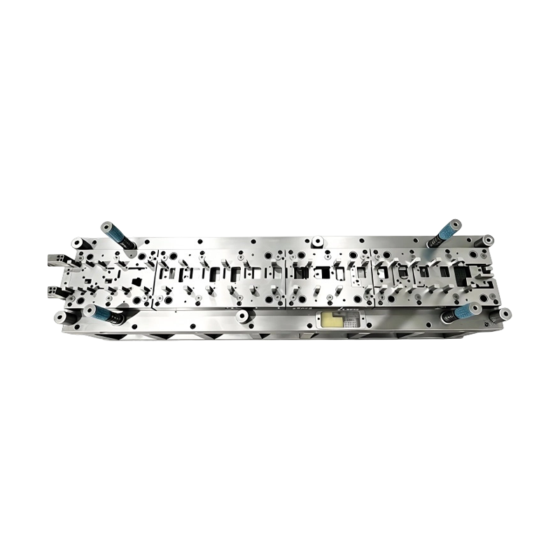
Long-Stroke Multi-Stage Progressive Die Automatic Strip Feed Progressive Die Long Travel Follow on Stamping Tool for Sheet Metal Hardware Press Moulding
Long-Stroke Multi-Stage Progressive DieOur custom ...
-
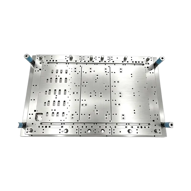
Multi-Station Progressive Stamping Die with Carbide Inserts Custom Multi Station Progressive Stamping Die Carbide Insert Metal Stamping Mold Tool for Equipment Appliances Device Hardware
High Speed Metal Stamping Tool for Precise Equipme...
-
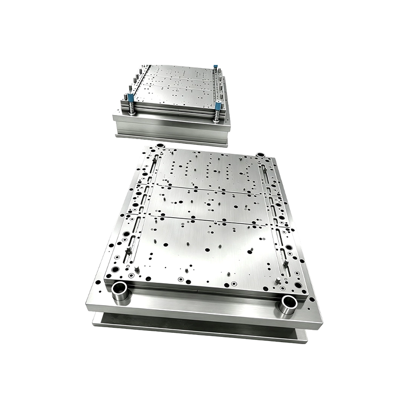
Progressive Stamping Die for Connector & Terminal Parts High Speed Progressive Stamping Die Precision Metal Hardware Stamping Tool mold for Connector Terminal Parts Automotive Components
Progressive Stamping Die for Connector & Termi...
-
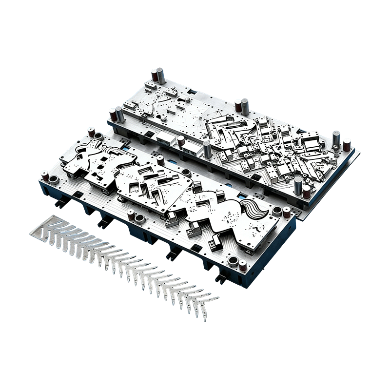
Progressive molds for automotive parts
This Continuous mold for automotive motor housing ...
-
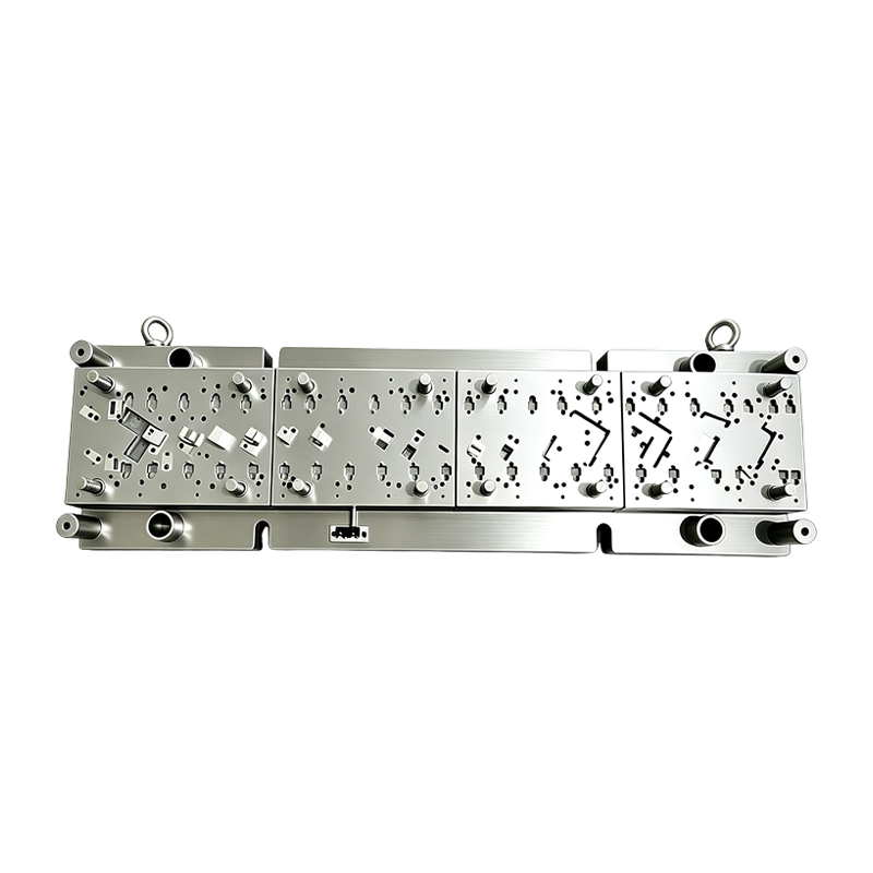
High Speed Progressive Stamping Die Sheet Metal Follow on Press Tool
Multi-operation Metal Stamping Tool for Continuous...
-
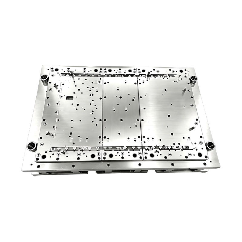
High Precision Stamping Die Multi Station Hardware Progressive Mold Tooling
Precision Metal Stamping Tool for Automotive &...
- E-mail us: [email protected]
- Call us: +86-139 1308 8972

Zhou Mengjie – Technical Sales Specialist
Home / Author / Zhou Mengjie – Technical Sales Specialist / Long-Stroke Multi-Stage Progressive Dies for Complex Sheet Metal Forming
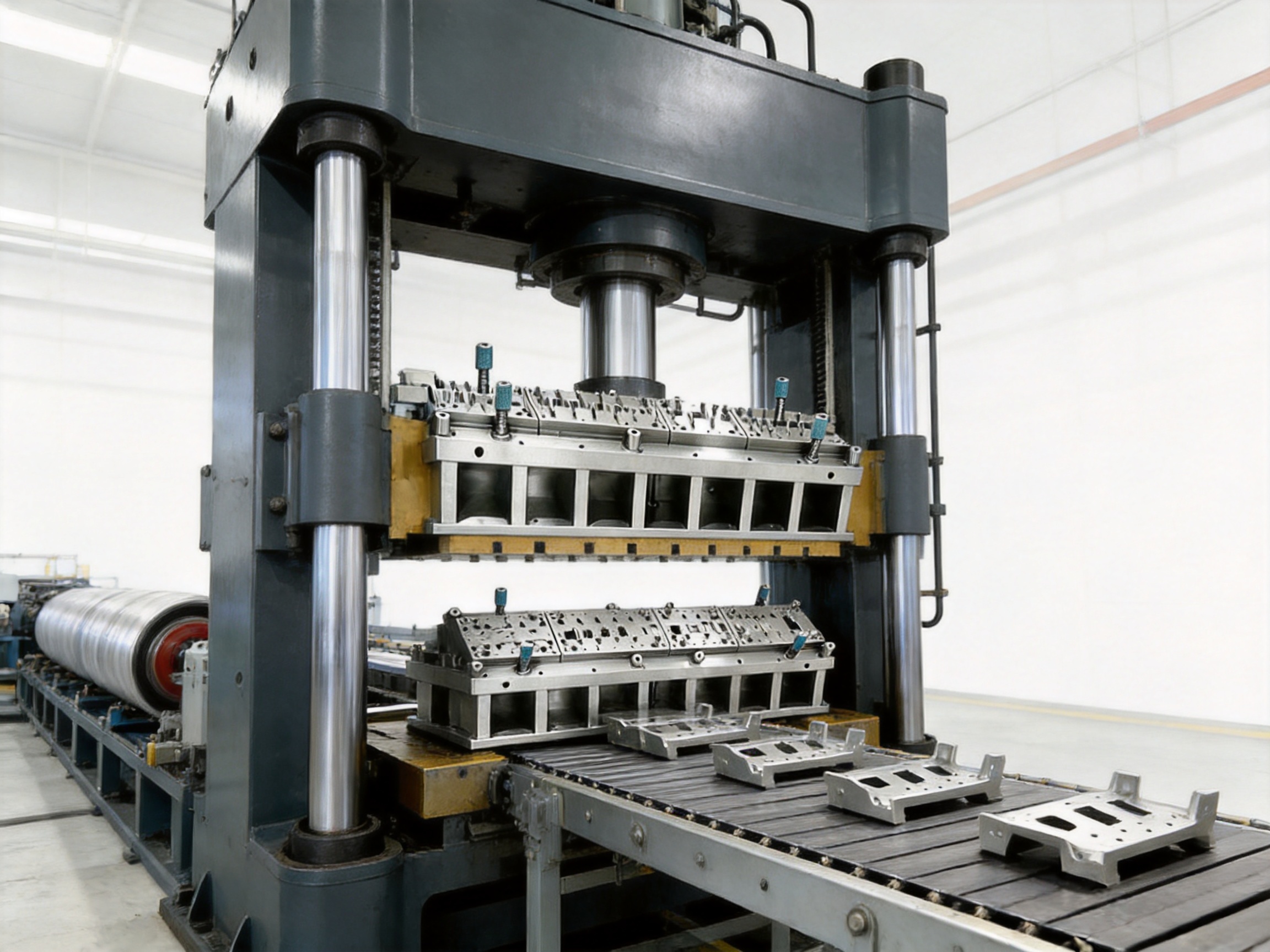
Long-Stroke Multi-Stage Progressive Dies for Complex Sheet Metal Forming
2026-11-05
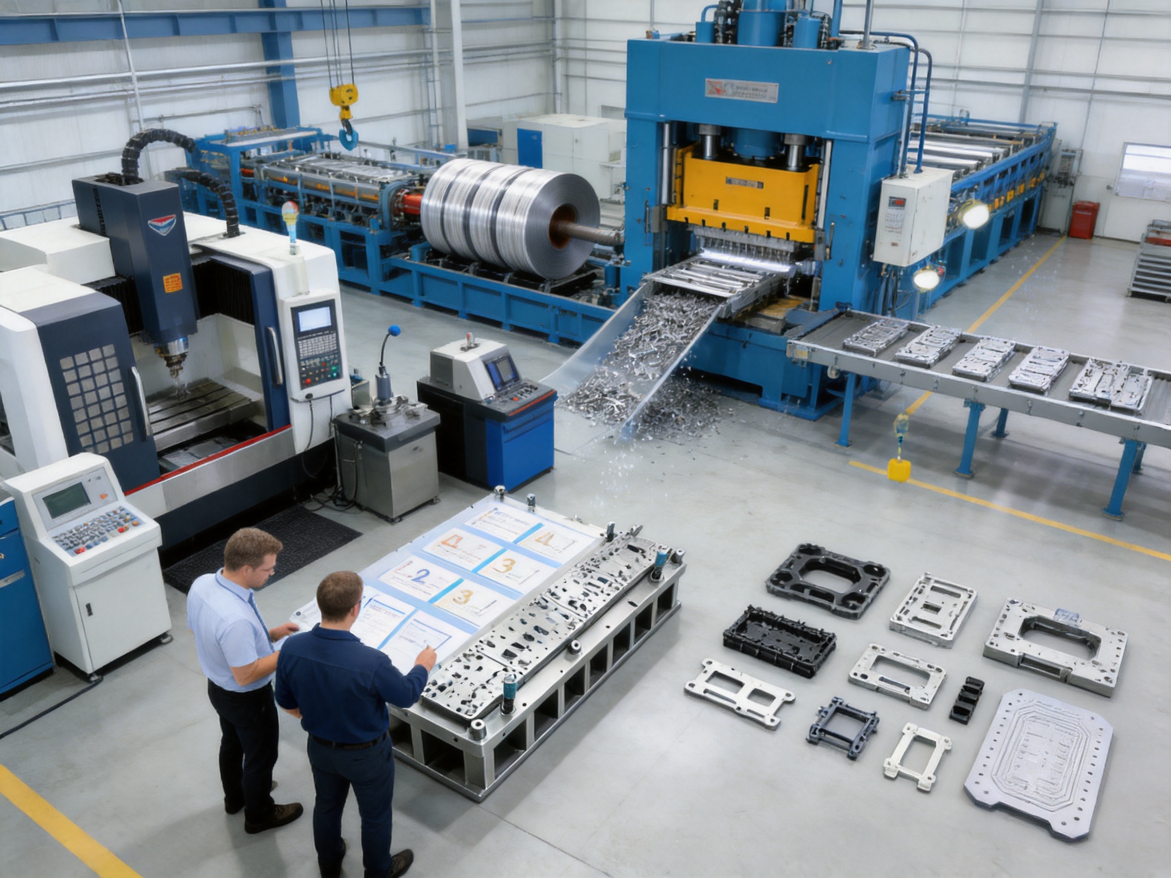
Modern automotive, electric vehicle, electrical, and industrial products increasingly depend on sheet metal components with complex three-dimensional geometry. A single part may require several pierced holes, multiple bends, offsets, embossments, coined surfaces, reinforcing ribs, and a precisely separated finished profile. Producing these features economically requires more than a conventional blanking tool. It requires a progressive die engineered to control the material through a carefully sequenced series of forming operations.
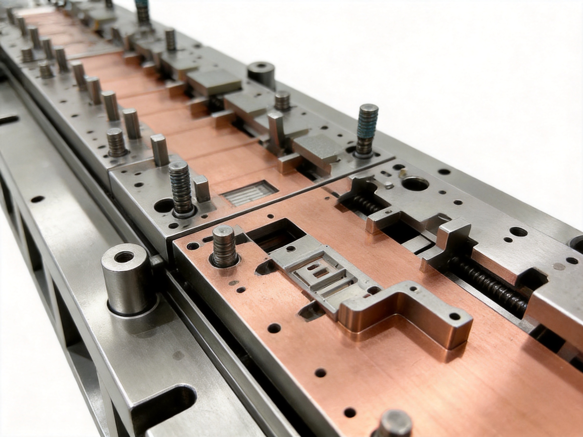
The long-stroke multi-stage progressive die is designed for this purpose. It combines automatic coil or strip feeding with a long working layout containing multiple forming stations. As the strip advances through the die, each station performs a controlled operation. Piercing, lancing, pre-bending, final bending, embossing, coining, restriking, and final blanking can be arranged in a single continuous production process.
This design is particularly suitable for automotive brackets, electric vehicle battery components, electrical connector parts, structural shields, sensor mounts, relay frames, clips, housings, and other sheet metal hardware that requires several forming stages. Instead of transferring unfinished parts between separate dies or relying on manual secondary operations, manufacturers can complete the component in one automated progressive run.
Designed and manufactured by Suzhou Shuangqisi Mold Equipment Co., Ltd., the die reflects an integrated approach to tooling, precision machining, tryout, production support, and stamping automation. The company combines mold design and manufacturing with stamping equipment capabilities, enabling customers to obtain a coordinated solution rather than an isolated tool.
Content
- 1 What Is a Long-Stroke Multi-Stage Progressive Die?
- 2 Why Long-Stage Forming Is Important for Complex Parts
- 3 Extended Multi-Station Layout
- 4 Sequential Bending and Springback Compensation
- 5 Long-Strip Stability and Anti-Warping Feed Control
- 6 Heavy-Duty Die Base and Multi-Point Guidance
- 7 Modular Forming Inserts for Faster Adjustment
- 8 Integrated Scrap Management and Part Ejection
- 9 Comparison with Conventional Short-Stage Dies
- 10 Manufacturing Capabilities and Engineering Strengths
- 11 Application Areas
- 12 Quality Control and Die Validation
- 13 Maintenance and Operating Considerations
- 14 Selection Factors for Buyers
- 15 Competitive Advantages of the Product
- 16 Project Development Process
- 17 Frequently Asked Questions
- 17.1 What types of parts are suitable for this die?
- 17.2 How many stations can the die contain?
- 17.3 Can the die produce three-dimensional parts?
- 17.4 How does the tool control springback?
- 17.5 Is the die suitable for high-strength steel?
- 17.6 How is strip movement controlled over the long die body?
- 17.7 What happens to piercing scrap?
- 17.8 How are finished parts removed?
- 17.9 Can individual stations be modified?
- 17.10 What manufacturing resources are available?
- 17.11 Can the company provide automation equipment?
- 17.12 What information should a customer provide before requesting a quotation?
- 18 Conclusion
- 19 References
- 20 Product: Long-Stroke Multi-Stage Progressive Die Automatic Strip Feed Progressive Die Long Travel Follow on Stamping Tool for Sheet Metal Hardware Press Moulding
What Is a Long-Stroke Multi-Stage Progressive Die?
A progressive die is a stamping tool containing several sequential stations. A metal strip is fed through the die at a predetermined pitch. At each press stroke, the strip moves to the next position, while different stations perform different operations on sections of the strip. Once the material reaches the final station, the finished part is separated from the carrier strip.
A long-stroke multi-stage progressive die extends this concept over a larger die body and a greater number of stations. The working layout may accommodate approximately eight to more than thirty forming stations, depending on the component design, material, thickness, and required operations. The extended layout creates enough space to distribute complicated forming sequences instead of forcing too many operations into a limited number of stations.
The term “long-stroke” refers to the extended travel and working arrangement required for long-distance strip progression and multi-stage forming. It does not simply mean that the press moves farther. The entire tool system—including the die base, guide structure, pilots, lifters, pressure pads, inserts, scrap routes, and ejection devices—must be engineered to maintain accuracy throughout the complete strip path.
A typical process may include the following sequence:
1. Strip entry and initial guiding.
2. Pilot hole piercing for accurate registration.
3. Preliminary piercing and lancing.
4. Notching and carrier preparation.
5. Embossing or local stiffening.
6. Pre-bending of one or more walls.
7. Secondary bending and offset formation.
8. Restriking and springback correction.
9. Coining or calibration of critical areas.
10. Final piercing, trimming, and profile cutting.
11. Final blanking and three-dimensional part ejection.
The exact station arrangement is developed around the part geometry. Some stations may be dedicated to cutting, while others are designed for forming, supporting, restriking, or controlling the strip. This flexibility allows the die to produce complex parts without unnecessary manual handling.
Long-Stroke Multi-Stage Progressive Die Automatic Strip Feed Progressive Die Long Travel Follow on Stamping Tool for Sheet Metal Hardware Press Moulding
Why Long-Stage Forming Is Important for Complex Parts
Many sheet metal parts cannot be formed accurately in a single bending operation. A sharp bend made too quickly may cause cracking, excessive springback, distortion, wrinkles, or loss of dimensional control. This is especially true when working with high-strength steel, stainless steel, thick-gauge stock, or narrow components with several nearby features.
A multi-stage progressive die divides the forming load into manageable steps. A pre-bend begins the shape, a later station develops the target angle, and a restriking or coining station corrects the final geometry. By distributing deformation, the tool can reduce localized stress and improve repeatability.
The long layout also gives designers more room to separate operations that might interfere with each other. A pierced feature can be completed before a wall is bent. An embossment can be formed before the surrounding area becomes inaccessible. A final calibration operation can be positioned near the end of the process, after most of the part geometry has been established.
This approach offers several production benefits:
• Complex components can be produced in a single automated sequence.
• Secondary bending and manual repositioning can be reduced or eliminated.
• Part-to-part consistency is improved through fixed station relationships.
• Production labor and handling requirements can be reduced.
• Scrap movement can be managed within the die layout.
• High-volume manufacturing becomes more practical.
• Tool adjustments can be concentrated in individual modular stations.
Extended Multi-Station Layout
The extended die body is one of the main differences between this product and a short, conventional progressive tool. A short die may be suitable for simple flat parts, basic blanking, or a small number of bends. However, when the component requires many operations, compressing the sequence into too few stations can create excessive forming loads and compromise strip control.
The long-stroke configuration provides additional station capacity. The die can be arranged with eight, ten, fifteen, twenty, or more stations, depending on the engineering requirements. Each station is assigned a specific function so that the complete process remains stable and logically sequenced.
Station spacing is determined by the geometry of the part, the required feed pitch, the material width, the carrier design, and the access needed for tooling components. Operations that generate considerable force can be separated from delicate piercing or calibration operations. Similarly, bends can be distributed along the strip so that previously formed features are not damaged by later tool movements.
The extended layout is also useful for parts with several independent forming directions. For example, a bracket may require a longitudinal bend, two side flanges, a reinforcing embossment, a mounting hole, and a final offset. Rather than forcing these features into one or two crowded stations, the die can form them progressively and verify their positioning through the fixed tool structure.
For electrical and electronic components, a long progressive die can accommodate narrow carriers, fine pierced features, terminal shapes, locking tabs, and multiple small bends. For automotive components, it can handle larger strip widths and heavier forming loads while maintaining controlled movement through the die.
Process Planning Based on Part Geometry
Successful progressive die design begins with process planning. Engineers study the part drawing, material grade, thickness, tolerance requirements, forming directions, grain orientation, hole locations, and production volume. They then determine the most suitable strip layout and station sequence.
The strip layout must balance material utilization with reliable feeding and sufficient carrier strength. A narrow carrier may save material but become unstable during long travel. A wider carrier may improve rigidity but increase scrap. The engineering objective is to achieve dependable transport, accurate registration, and acceptable material yield at the same time.
Forming order is equally important. Features that provide useful reference points may be made early in the process. Features vulnerable to distortion may be delayed until the strip has adequate support. Final cuts are positioned so that the finished part separates cleanly without damaging adjacent components or leaving excessive burrs.
Sequential Bending and Springback Compensation
Springback is one of the most important challenges in sheet metal forming. After the forming force is released, elastic recovery causes the material to move away from the intended shape. The amount of springback depends on material strength, thickness, bend radius, grain direction, forming angle, tooling condition, and deformation history.
A single-hit bend may not provide sufficient control for a demanding component. The long-stroke die addresses this issue through sequential forming. A first station creates a controlled pre-bend. A following station increases the angle or develops another wall. A restriking station then applies additional pressure to stabilize the final position. Where necessary, coining or localized calibration is used to improve dimensional consistency.
This progressive approach can reduce variation in bend angles and wall positions. It is especially useful for high-strength steel, stainless steel, and thicker materials, where springback can be more pronounced. Instead of relying on one large deformation, the process manages the material through several smaller and more predictable changes.
Springback compensation may include modified forming angles, over-bending, restrike surfaces, local coining, controlled radii, and carefully timed support. These solutions are incorporated into the insert geometry and verified during die tryout. The final method depends on the customer’s material specification and the required part tolerances.
Benefits of Distributed Forming
Distributed forming reduces the risk of sudden deformation and helps maintain strip stability. It can also lower the peak load required at one station, allowing the press capacity to be used more effectively. Since each stage has a defined purpose, process adjustments can be made more precisely during commissioning.
For example, if a flange angle is slightly open, the corresponding pre-bend or restrike insert can be adjusted without redesigning every station. If a hole shifts after bending, the sequence can be reviewed and the relevant pilot, support, or forming surface can be modified. This station-based approach simplifies troubleshooting compared with a tool in which many operations are concentrated together.
Long-Strip Stability and Anti-Warping Feed Control
Long progressive dies require reliable strip control. As the material travels through many stations, it may become more difficult to keep the strip flat and correctly aligned. Piercing, bending, embossing, and partial separation can change the stiffness of the carrier. If the strip lifts, twists, or warps, subsequent stations may produce dimensional errors or collide with the material.
The die incorporates multiple methods for maintaining strip stability. Precision pilot pins are positioned at suitable intervals to register the strip and control pitch. Strip lifters support the material between forming operations and assist with smooth movement during die opening. Pressure pads help hold areas close to the forming zone, while guide rails control lateral movement along the extended path.
These elements work together rather than relying on a single guide feature. Pilot pins establish position. Lifters help maintain elevation. Pressure pads restrain local movement. Guide rails support the strip edge and prevent lateral wandering. The combination is particularly valuable when the strip has passed through more than fifteen stations and has already undergone significant deformation.
Feed stability also depends on correct timing between the automatic feeder and the press. The strip must advance only when the die is safely open and must reach the correct pitch before the next stroke. Sensors, pilots, lifters, and feeder settings should be coordinated during setup and validated during tryout.
Heavy-Duty Die Base and Multi-Point Guidance
A long die body must resist deflection and maintain parallelism across its entire working length. Conventional corner guidance alone may not be sufficient for an extended tool with multiple high-load forming stations. Uneven force distribution can cause localized deflection, clearance changes, or what is sometimes described as a “banana effect,” in which the die assembly bends or loses consistent alignment along its length.
The long-stroke die is built on a stress-relieved, precision-ground die base. Multiple guide pillar sets are distributed along the die rather than being placed only at the four corners. This multi-point guidance supports the upper and lower die sections across the full working area.
Uniform guidance helps maintain cutting clearance, bend depth, and insert alignment from the first station to the final station. It also reduces the risk that a heavy forming load at one end of the tool will disturb the operating relationship at another end.
Die base rigidity is supported by appropriate material selection, machining accuracy, stress-relief procedures, support layout, and controlled assembly. The exact construction is adapted to the press size, component dimensions, material thickness, and expected production volume.
Importance of Precision Grinding
Precision grinding is essential for surfaces that determine die height, insert positioning, cutting clearance, and parallelism. Even when individual components are manufactured accurately, the complete die must be assembled and verified as a system. Grinding and fitting operations help ensure that the forming stations work together within the specified process requirements.
The manufacturer operates more than ten grinding machines of various sizes, in addition to CNC machining centers, wire-cutting equipment, and a range of punch presses. This equipment base supports the production of complex die components and enables important machining and finishing work to be managed within an integrated manufacturing environment.
Modular Forming Inserts for Faster Adjustment
Each forming station may use independently replaceable modular inserts. This design allows engineers and maintenance personnel to focus on the station that requires attention rather than dismantling the complete die. If a bend needs correction, the affected insert can be adjusted or replaced. If a customer changes the component design, the relevant station can be modified with less disruption to the rest of the tool.
Modular inserts can also simplify spare-part planning. Wear-prone components may be produced as replaceable units, reducing the time required for maintenance. During production, a damaged or worn cutting element can be changed without replacing a large section of the die body.
The modular philosophy is particularly valuable during tryout. Complex progressive dies often require controlled adjustments after the first stamping samples are inspected. Bend angles, hole positions, trim conditions, and material flow may require fine tuning. Separate inserts allow these changes to be performed with greater efficiency.
Modularity provides the following practical advantages:
• Reduced adjustment time during die commissioning.
• Easier replacement of worn or damaged components.
• Lower maintenance disruption.
• Improved adaptability to material lot variation.
• Faster response to engineering changes.
• More efficient management of spare tooling components.
Integrated Scrap Management and Part Ejection
Progressive stamping creates scrap at piercing, notching, trimming, and blanking stations. In a long tool, scrap control must be planned carefully because slugs that remain inside the die may interfere with later operations, damage the material, or cause production stoppages.
Internal scrap chutes direct slugs toward designated discharge points. The chute arrangement is developed around the station layout so that scrap can leave the working area without obstructing pilots, inserts, carriers, or moving components. Effective scrap management is especially important when multiple piercing stations operate in succession.
At the final blanking station, the finished three-dimensional part can be removed using air blow-off or a mechanical kicker. The selected ejection method depends on the part’s shape, weight, surface requirements, and downstream handling system. The part may be directed to a conveyor or collection system for inspection, packaging, or the next manufacturing operation.
Automated ejection reduces the need for operators to reach into the press area and supports continuous production. It also helps prevent finished parts from accumulating inside the die, where they could be struck by the next stroke or interfere with the strip.
Comparison with Conventional Short-Stage Dies
Short-stage terminal dies and simple progressive dies remain useful for uncomplicated components. They may be economical when the part requires only blanking, one or two bends, or a limited number of holes. However, they are not always suitable for components with many forming features and demanding three-dimensional geometry.
The long-stroke multi-stage die offers a different production strategy. It uses additional die length and more stations to distribute operations. This can increase initial tooling complexity, but it may reduce the need for multiple tools, secondary operations, and manual transfers.
| Evaluation Area | Short or Simple Die | Long-Stroke Multi-Stage Progressive Die |
|---|---|---|
| Typical part complexity | Flat parts or parts with limited forming | Complex three-dimensional components |
| Number of operations | Small number of blanking or bending steps | Multiple piercing, bending, embossing, coining, and trimming steps |
| Station capacity | Limited working length | Approximately 8 to more than 30 stations, depending on design |
| Springback control | Often limited to one forming hit | Pre-bend, final bend, restrike, and coining stages |
| Strip control | Suitable for short travel | Multiple pilots, lifters, pressure pads, and guide rails |
| Changeover and repair | May require larger tool modifications | Modular inserts permit targeted changes |
| Production handling | May require secondary transfer or manual handling | Automatic strip feed and integrated part ejection |
| Best application | Simple, low-feature components | High-volume complex sheet metal hardware |
The correct choice depends on part geometry, annual volume, material, tolerance, press availability, and investment objectives. The long-stroke tool is not intended to replace every type of stamping die. Its advantage appears when a component contains enough sequential operations that an integrated automated process becomes more efficient and reliable than separate operations.
Manufacturing Capabilities and Engineering Strengths
Suzhou Shuangqisi Mold Equipment Co., Ltd. provides stamping die design, manufacturing, hardware part production, and stamping automation support. The company has approximately fifteen years of experience in the mold industry and employs around sixty technical staff. Its capabilities cover the path from initial tooling development to machining, assembly, debugging, and production support.
The company’s equipment includes imported wire-cutting machines, CNC machining centers, more than ten grinding machines of different sizes, and twenty-five punch presses ranging from 80 tons to 400 tons. This combination supports both precision tool production and practical stamping verification.
Wire cutting is suitable for producing intricate profiles and hardened die components with controlled geometry. CNC machining centers provide efficient production of die plates, holders, forming blocks, and structural components. Grinding equipment supports the precision finishing required for working surfaces, reference planes, and assembly interfaces. The punch press range allows the company to perform trials and evaluate tools under representative forming conditions.
Integrated Design and Manufacturing
Keeping design, machining, assembly, and tryout closely connected can improve communication and shorten feedback cycles. Toolmakers can review forming results directly, identify areas requiring adjustment, and implement changes with a clear understanding of the manufacturing process.
This integrated approach is important for long progressive dies because performance depends on the relationship between many elements. A small error in pilot timing, insert height, carrier support, or clearance can influence several downstream stations. Coordinated engineering and production teams can evaluate these relationships more efficiently than a fragmented supply chain.
The company’s senior operators and experienced debugging personnel contribute practical knowledge during assembly and trial production. Their work includes checking strip movement, validating station timing, examining part quality, confirming scrap discharge, and making controlled adjustments to the forming inserts.
Stamping Automation Integration
In 2016, the company invested in and established Suzhou Keshuang Intelligent Technology Co., Ltd., which focuses on stamping automation equipment. This development supports the integration of molds with automatic feeding, transfer, ejection, and production-line equipment.
For customers, the benefit is the possibility of obtaining a more complete solution. Instead of purchasing a die from one source and attempting to coordinate automation separately, customers can discuss the tooling and production equipment as a connected system. The company can also invest in related production equipment according to customer requirements when a broader turnkey arrangement is appropriate.
Automation integration is particularly relevant to long-stroke progressive dies. The tool must work in coordination with the coil feeder, decoiler, straightener, press controls, sensors, conveyors, scrap systems, and safety devices. Consistent communication between the die designer and automation provider helps reduce interface risks.
Application Areas
The long-stroke multi-stage progressive die is suited to industries that require repeatable, high-volume sheet metal components.
Automotive and Electric Vehicles
Automotive applications may include seat brackets, door panel clips, hinge components, sensor mounting brackets, brake line clips, structural reinforcement plates, connector housings, and other body or interior hardware. Electric vehicle applications may include battery module brackets, busbar support frames, cooling-system clips, motor housing components, charging connector parts, and mounting hardware.
These applications often require high repeatability, stable bend angles, accurate hole locations, and reliable production over long runs. The multi-stage process can support these requirements by combining controlled forming with automatic feeding and fixed station relationships.
Electrical and Electronics
Electrical and electronic components may include relay frames, terminal blocks, switch housings, EMI shielding cans, PCB mounting clips, connector shells, and small stamped brackets. These parts can contain narrow walls, tabs, pierced features, and precise interlocking shapes.
The modular insert structure is useful when small features require adjustment during tryout. Controlled pilots and pressure pads help maintain the registration necessary for fine-pitch electrical components.
Telecommunications and Data Centers
Telecommunications and data center hardware may include server chassis brackets, cable management clips, heat sink mounting parts, rack hardware, and shielding frames. These products often demand repeatable dimensions and stable assembly relationships because components must fit into standardized enclosures.
Home Appliances
Home appliance applications may include washer drum brackets, compressor mounting plates, hinge components, control panel frames, and motor support structures. Long progressive dies can help reduce the number of separate operations required for these medium-sized formed parts.
Industrial Automation
Industrial equipment manufacturers may use the die for sensor brackets, actuator clips, conveyor components, relay sockets, terminal strip housings, and other functional hardware. The integrated production method can support stable supply for equipment builders with recurring component demand.
Aerospace-Related Components
Possible aerospace-related applications include lightweight bracket preforms, clip fasteners, and structural sheet metal components. When used for aerospace programs, the tooling, materials, inspection procedures, documentation, and qualification requirements must be aligned with the customer’s applicable standards. The company identifies AS9100 compatibility as a relevant capability for suitable projects, subject to project-specific requirements.
Quality Control and Die Validation
Quality control begins with reviewing the part drawing, material specification, tolerance requirements, and production objectives. Before machining, the process plan should confirm the strip layout, station sequence, forming direction, pilot strategy, scrap routes, and ejection method.
During manufacturing, critical components are checked for dimensional accuracy and surface condition. Assembly checks confirm that guide pillars, inserts, plates, pressure pads, lifters, and cutting elements operate correctly. The completed die is then tested through a controlled tryout process.
Tryout samples are evaluated for hole position, bend angle, flange height, profile accuracy, burr condition, surface marks, cracks, wrinkles, and overall dimensional stability. The strip’s movement through the complete die is also observed. Any required adjustments should be recorded and applied systematically rather than through uncontrolled trial and error.
Long progressive tools benefit from validation at several levels:
• Individual insert verification.
• Die assembly and parallelism checks.
• Manual or low-speed movement checks.
• Initial press tryout.
• Automatic feed and pilot verification.
• Continuous run testing.
• Finished-part inspection.
• Scrap and ejection confirmation.
Production approval should consider both part quality and process stability. A tool that produces one acceptable sample but experiences frequent strip misfeeds or scrap blockages is not fully optimized. The objective is a reliable production system that can maintain quality over repeated press cycles.
Maintenance and Operating Considerations
Regular maintenance is essential for preserving the accuracy of a long progressive die. Operators should inspect pilots, guide components, lifters, pressure pads, springs, cutting edges, forming inserts, and scrap chutes according to an established schedule.
Wear on pilot pins or guide surfaces can gradually affect registration. Dull cutting edges may increase burrs and force requirements. Contamination in scrap chutes can cause slug buildup. Damaged lifters or pressure pads can allow the strip to lift or twist. Early detection helps prevent secondary damage to the die and reduces unplanned downtime.
Lubrication should follow the requirements of the die and the stamped material. Excessive lubricant may affect downstream processes, while insufficient lubrication can increase wear and galling. Press settings, feeder pitch, coil alignment, and sensor operation should also be checked when the tool is installed or moved to another production line.
The modular insert concept simplifies maintenance because many wear parts can be replaced individually. A documented spare-parts list can further reduce response time. Customers producing large volumes may benefit from maintaining spare pilot pins, cutting inserts, forming inserts, springs, and other high-use components.
Selection Factors for Buyers
Before commissioning a long-stroke progressive die, buyers should provide complete technical information. Important details include part drawings, three-dimensional models, material grade, thickness, coil width, tensile strength, grain direction, tolerance requirements, annual production volume, available press specifications, feeder type, and downstream handling requirements.
The press must have sufficient tonnage, stroke, shut height, bed size, operating speed, and energy capacity. The die length and width must fit the press table, and the feeder must be able to achieve the required pitch with stable acceleration and deceleration.
Buyers should also define inspection standards and acceptance criteria. These may include dimensional reports, sample quantities, surface requirements, burr limits, capability studies, production speed, and continuous-run duration. Early agreement helps align design decisions with the final manufacturing objective.
| Input Required | Why It Matters |
|---|---|
| Part drawing and 3D model | Defines geometry, forming directions, tolerances, and critical features |
| Material grade and thickness | Determines forming behavior, springback, force, and insert design |
| Production volume | Influences automation level, wear protection, and spare-part planning |
| Press specifications | Confirms available tonnage, stroke, shut height, and installation space |
| Coil and strip information | Supports strip layout, carrier design, feeder selection, and material utilization |
| Quality requirements | Establishes inspection methods, acceptance limits, and validation procedures |
| Downstream process information | Guides part ejection, conveyor design, packing, and further assembly |
Competitive Advantages of the Product
The primary advantage of the long-stroke multi-stage progressive die is its ability to combine many operations in one automated tool. Competitors offering only short-stage blanking or basic bending tools may require additional dies, manual transfers, or secondary forming equipment for the same part.
Another advantage is the controlled distribution of forming operations. Pre-bending, final bending, restriking, and coining can be arranged to manage springback and improve dimensional consistency. This is valuable for materials that are difficult to form accurately in a single operation.
The multi-point guide structure provides an advantage over long dies that rely only on corner guidance. Distributed support helps preserve parallelism and working clearance along the complete die body. The anti-warping strip system further supports stable feeding after the strip has undergone many deformations.
Modular inserts create a practical advantage during tool development and maintenance. Instead of modifying a large monolithic structure, the manufacturer can concentrate changes on the affected station. This may reduce tryout time and make future design revisions more manageable.
Integrated scrap management and part ejection support uninterrupted automated production. Scrap is directed away from the working area, while finished parts are removed by air blow or mechanical kicker. This reduces manual intervention and helps maintain a safer, cleaner press operation.
Finally, the manufacturer’s combined capabilities in mold production, stamping, machining, and automation allow customers to discuss tooling and equipment as one production solution. This integrated capability can simplify communication, reduce coordination problems, and support more efficient project execution.
Project Development Process
A typical project begins with a technical review of the component and production goals. The engineering team evaluates the material, part complexity, press conditions, annual volume, and automation expectations. A preliminary process plan and strip layout are then developed.
After the process direction is approved, detailed die design begins. The design includes station sequencing, forming inserts, pilots, guide pillars, lifters, pressure pads, scrap chutes, ejection components, sensors, and interfaces with the automatic feeder and press.
Manufacturing follows with material preparation, rough machining, CNC machining, wire cutting, heat treatment or stress-relief processes where applicable, grinding, component inspection, and assembly. The die is then installed for tryout and evaluated using the specified sheet material.
Tryout feedback is used to refine springback compensation, trim conditions, feeding stability, part ejection, and other process details. Once the tool reaches the required performance level, production samples and documentation are prepared for customer review.
After approval, the company can support installation, operating guidance, maintenance recommendations, spare parts, and related stamping automation requirements. This continuing support is important because the value of a progressive die depends on its performance throughout the production lifecycle, not only on its initial delivery.
Frequently Asked Questions
What types of parts are suitable for this die?
The die is suitable for complex sheet metal components requiring multiple sequential operations. Examples include automotive brackets, electrical clips, connector housings, structural shields, battery module brackets, sensor mounts, relay frames, terminal components, and industrial hardware.
How many stations can the die contain?
The extended die body can accommodate approximately eight to more than thirty forming stations, depending on the part design, material, strip layout, production volume, and required operations. The final station count is determined during process engineering.
Can the die produce three-dimensional parts?
Yes. The die is designed for parts requiring multiple bends, offsets, embossments, pierced features, restriking, coining, and final blanking. The forming sequence gradually develops the three-dimensional geometry as the strip moves through the stations.
How does the tool control springback?
Springback is addressed through staged forming. Pre-bending, final bending, over-forming, restriking, and coining may be used according to the material and geometry. The exact compensation strategy is determined during design and verified during tryout.
Is the die suitable for high-strength steel?
It can be designed for high-strength steel, stainless steel, thick-gauge materials, and other demanding sheet materials, provided that the material specification and forming requirements are reviewed in advance. The tooling structure, forming radii, clearances, and press capacity must be matched to the material.
How is strip movement controlled over the long die body?
Strip control uses precision pilot pins, lifters, pressure pads, guide rails, and coordinated automatic feeding. These elements help prevent lifting, twisting, lateral movement, and warping during long-distance progression.
What happens to piercing scrap?
Internal scrap chutes guide slugs from piercing and trimming stations to designated discharge points. The chute layout is designed to prevent scrap buildup and reduce the risk of jamming during continuous operation.
How are finished parts removed?
Finished parts can be ejected using air blow-off or a mechanical kicker. The selected method depends on part geometry, weight, surface requirements, and the customer’s conveyor or collection arrangement.
Can individual stations be modified?
Yes. Modular forming inserts allow individual stations to be adjusted or replaced. This supports faster tryout corrections, maintenance, material-lot compensation, and future part design changes.
What manufacturing resources are available?
The manufacturer operates imported wire-cutting machines, CNC machining centers, more than ten grinding machines, and twenty-five punch presses ranging from 80 tons to 400 tons. The company also has technical personnel, senior operators, and debugging staff experienced in stamping die production.
Can the company provide automation equipment?
Yes. The company has an associated stamping automation capability established through Suzhou Keshuang Intelligent Technology Co., Ltd. Customers may discuss automatic feeding, ejection, conveyors, and related production equipment together with the die project.
What information should a customer provide before requesting a quotation?
Customers should provide the part drawing or three-dimensional model, material grade, thickness, annual volume, tolerance requirements, coil information, available press specifications, required production speed, and any special inspection or automation requirements.
Conclusion
The long-stroke multi-stage progressive die is a specialized solution for manufacturers that need to produce complex sheet metal parts efficiently and consistently. Its extended station layout allows piercing, bending, forming, embossing, coining, restriking, trimming, and blanking to be organized into one automated progression.
Its main technical strengths include distributed forming for springback control, long-strip stability through multiple guiding elements, heavy-duty construction with multi-point guidance, modular forming inserts, integrated scrap discharge, and automatic finished-part ejection. Together, these features address the challenges that arise when a strip travels through many forming stations.
The product is particularly valuable in automotive, electric vehicle, electrical, electronics, telecommunications, appliance, industrial automation, and suitable aerospace-related applications. It can reduce secondary operations, manual handling, and tool-to-tool transfers while supporting high-volume production.
Suzhou Shuangqisi Mold Equipment Co., Ltd. strengthens this product offering through integrated design, precision machining, grinding, stamping tryout, experienced debugging, and automation support. Its equipment base, technical staff, production resources, and related stamping automation capabilities provide customers with a foundation for complete tooling and manufacturing solutions.
For manufacturers evaluating a progressive die for a demanding sheet metal component, the key consideration is not simply the number of stations. The complete system must maintain material control, forming accuracy, structural rigidity, scrap removal, ejection reliability, maintainability, and compatibility with the customer’s press and automation line. A properly engineered long-stroke multi-stage progressive die addresses these requirements as one coordinated production platform.
References
1. Suzhou Shuangqisi Mold Equipment Co., Ltd. Product and company information supplied for technical content development.
2. American Society of Mechanical Engineers. General principles of metal forming and stamping die design.
3. Society of Manufacturing Engineers. Sheet Metal Forming and Progressive Die Manufacturing Practices.
4. ASM International. Materials Selection and Forming Considerations for Sheet Metal Components.
5. Standard industry practices for progressive die strip layout, pilot positioning, springback compensation, scrap control, and automated press operation.
Product: Long-Stroke Multi-Stage Progressive Die Automatic Strip Feed Progressive Die Long Travel Follow on Stamping Tool for Sheet Metal Hardware Press Moulding
Previous Post
No previous article
Next Post
Heavy Truck Stamping Parts: Precision Components for Reliable Commercial Vehicles
Our Products.
Start Your Business with an OEM Manufacturer Right Here!

Provide global customers with complete turn-key solutions
through
innovation!
QUICK LINKS
CONTACT INFO.
-
 +86-139 1308 8972
-

-
 No. 118 Yexin Road, Wujiang Economic Development Zone, Suzhou, China
Copyright © Suzhou Shuangqisi Mold Equipment Co., Ltd. All Rights Reserved. Custom Stamping Die Metal Stamping Die Manufacturers
