 English
 Español
 Deutsch

-
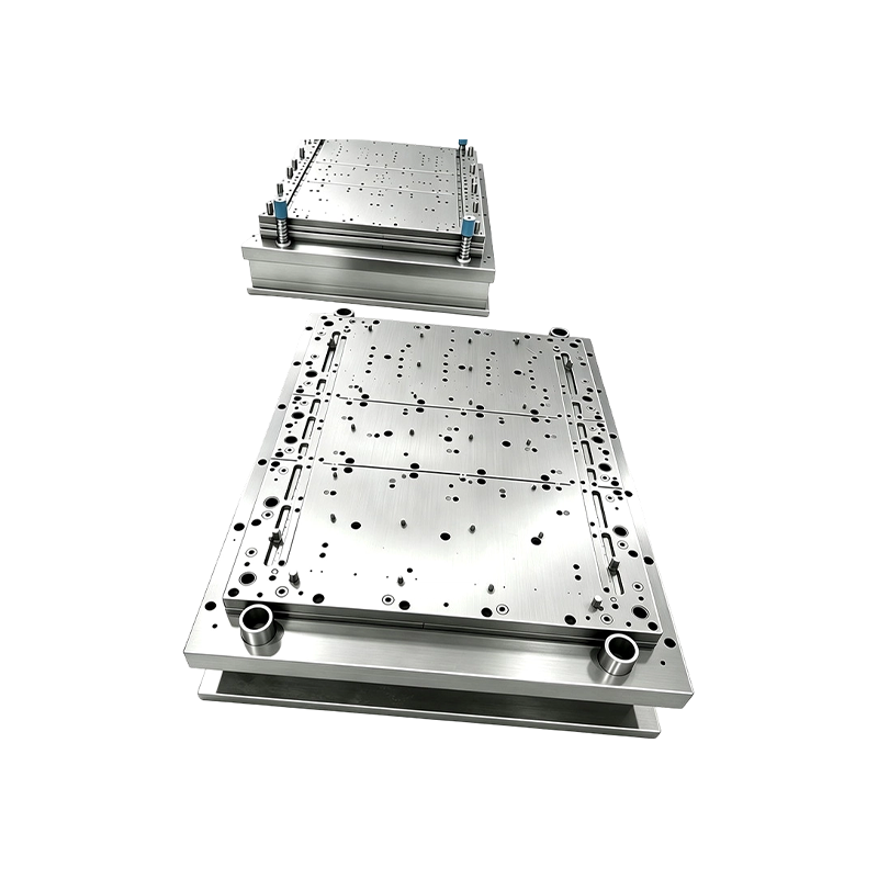
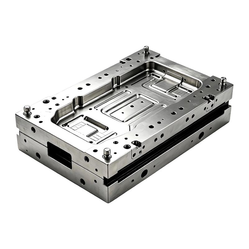
Progressive Stamping Die for Connector & Terminal Parts High Speed Progressive Stamping Die Precision Metal Hardware Stamping Tool mold for Connector Terminal Parts Automotive Components
Progressive Stamping Die for Connector & Termi...
-
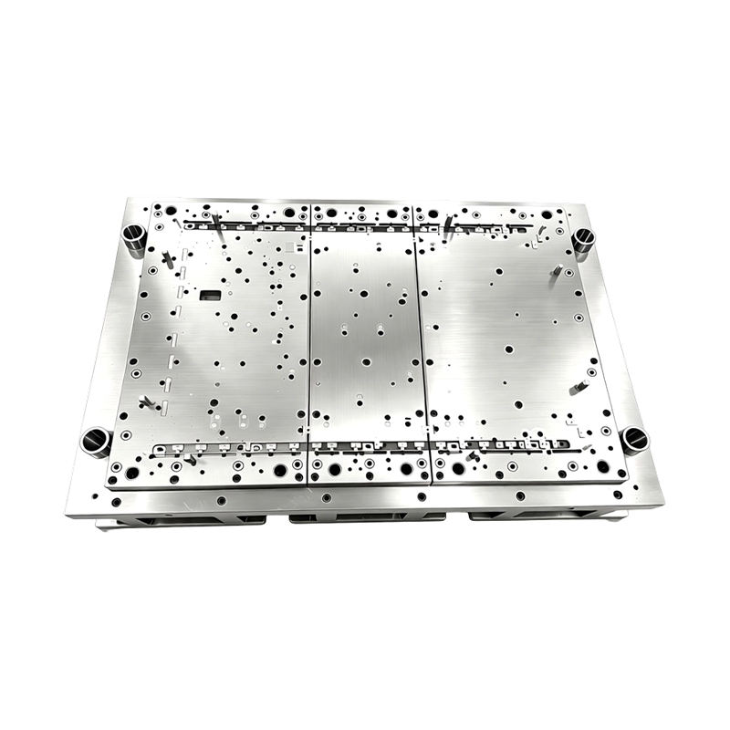
High Precision Stamping Die Multi Station Hardware Progressive Mold Tooling
Precision Metal Stamping Tool for Automotive &...
-
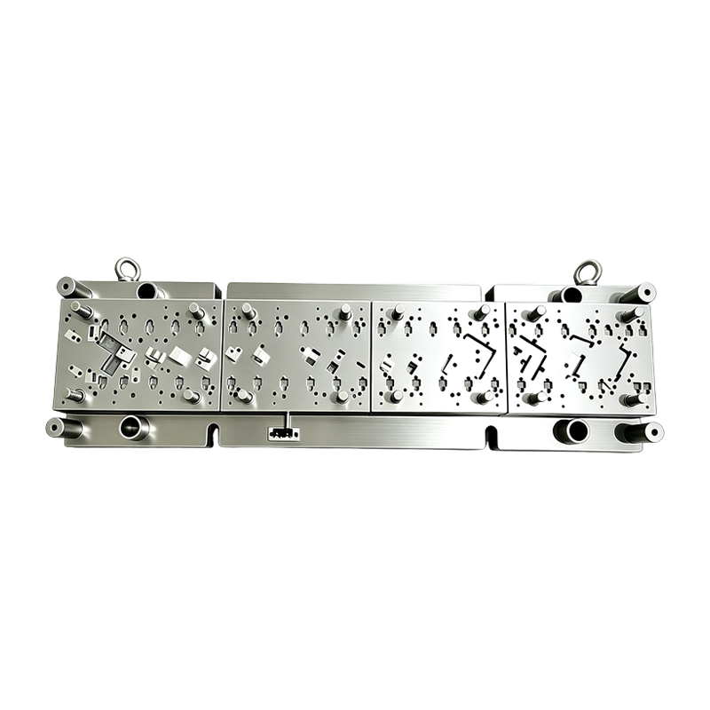
High Speed Progressive Stamping Die Sheet Metal Follow on Press Tool
Multi-operation Metal Stamping Tool for Continuous...
-
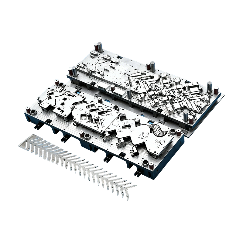
Progressive molds for automotive parts
This Continuous mold for automotive motor housing ...
-
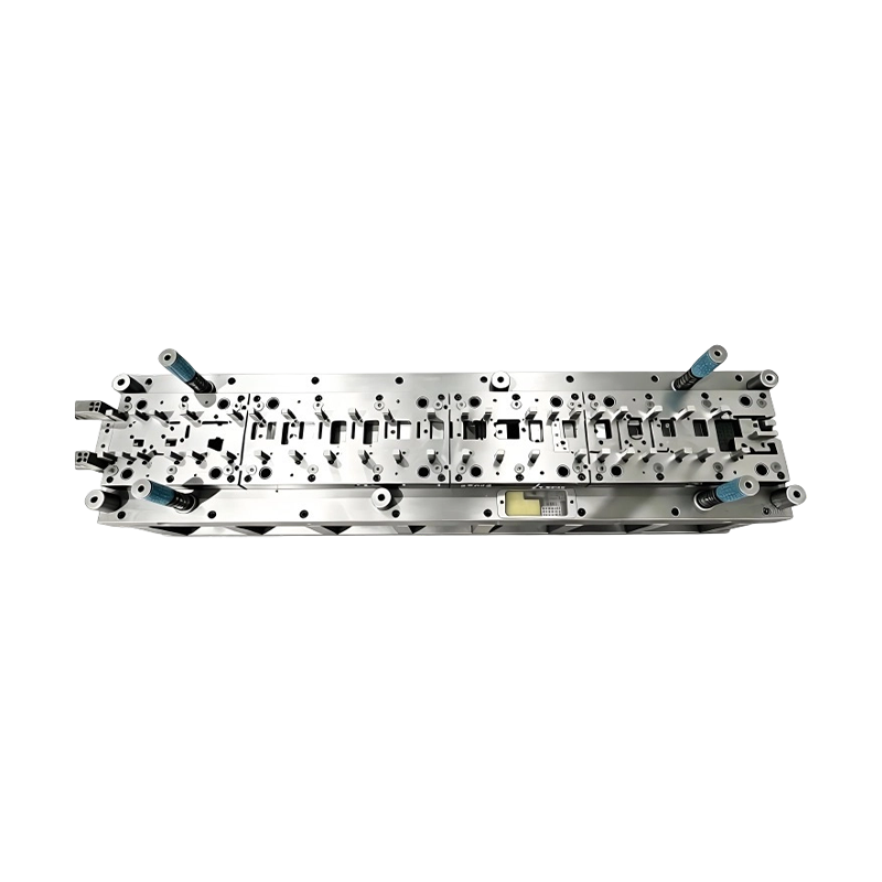
Long-Stroke Multi-Stage Progressive Die Automatic Strip Feed Progressive Die Long Travel Follow on Stamping Tool for Sheet Metal Hardware Press Moulding
Long-Stroke Multi-Stage Progressive DieOur custom ...
-
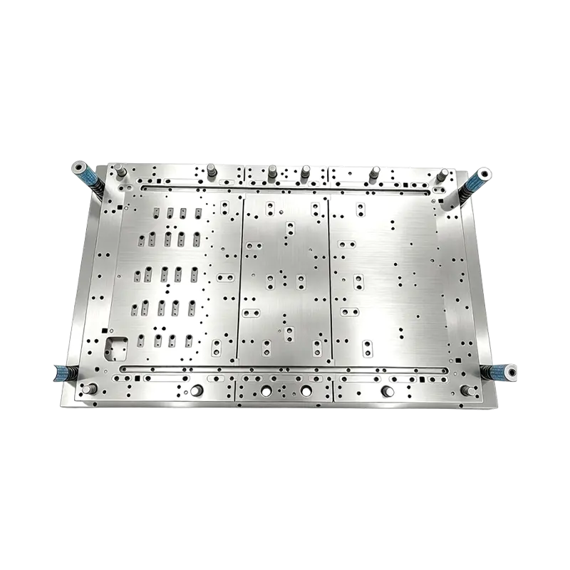
Multi-Station Progressive Stamping Die with Carbide Inserts Custom Multi Station Progressive Stamping Die Carbide Insert Metal Stamping Mold Tool for Equipment Appliances Device Hardware
High Speed Metal Stamping Tool for Precise Equipme...
- E-mail us: [email protected]
- Call us: +86-139 1308 8972

Liu Yanan – After-Sales Service Engineer
Home / Author / Liu Yanan – After-Sales Service Engineer / High-Speed Progressive Stamping Dies for Precision Connector, Terminal, and Automotive Components
High-Speed Progressive Stamping Dies for Precision Connector, Terminal, and Automotive Components
2026-09-22
Modern electrical, automotive, and electronic products depend on metal components that are small, accurate, repeatable, and economical to manufacture. Connector terminals, spring contacts, conductive parts, sensor components, shielding elements, and automotive electrical hardware may appear simple, but their production often requires extremely precise control of strip feeding, piercing, forming, bending, embossing, and final separation. A minor dimensional error can affect electrical conductivity, insertion force, assembly alignment, durability, or overall product safety.
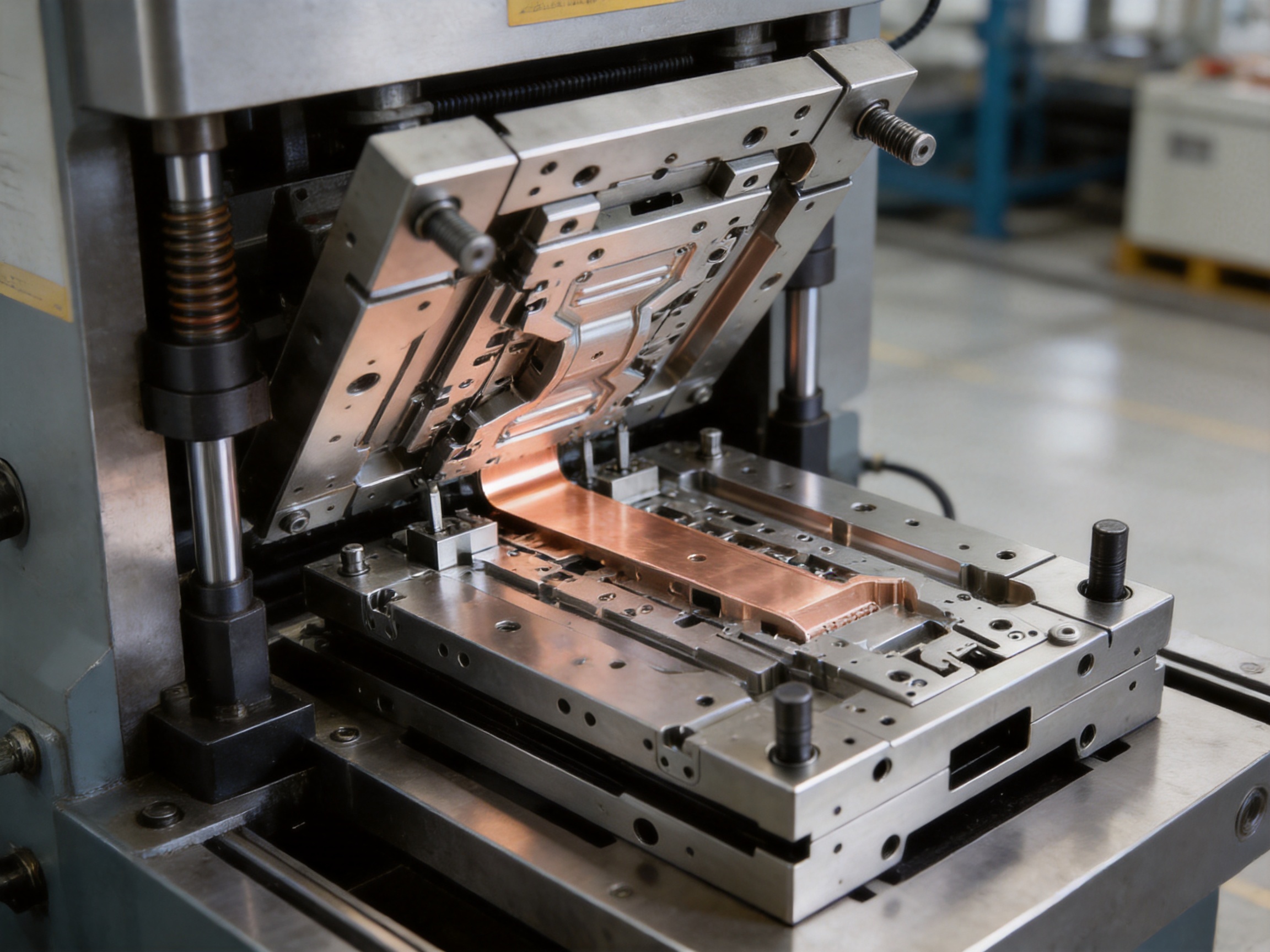
A high-speed progressive stamping die provides an efficient solution for these demanding applications. Instead of using several independent tools for separate operations, a progressive die integrates multiple stations into one coordinated stamping system. A metal strip is fed continuously through the die, and each press stroke performs a specific operation. As the strip advances, a partially formed component moves from one station to the next until the finished part is produced at the final station.
The progressive stamping die described in this article is engineered for high-volume production of precision metal hardware. It is suitable for connector and terminal parts, electronic contacts, automotive components, energy-related conductive parts, and other small metal components requiring stable tolerances and long production life. Its design combines high-precision pilot positioning, carbide cutting and forming inserts, rigid guide structures, modular construction, optimized scrap removal, and comprehensive customization.
In addition to the product’s technical features, the manufacturing capability behind the tool is a major advantage. Suzhou Shuangqisi Mold Equipment Co., Ltd. integrates stamping die design, precision machining, assembly, tryout, stamping production support, and automation equipment development. This integrated approach allows customers to obtain not only a die, but also a coordinated manufacturing solution for continuous stamping and automated production.
Progressive Stamping Die for Connector & Terminal Parts High Speed Progressive Stamping Die Precision Metal Hardware Stamping Tool mold for Connector Terminal Parts Automotive Components
Content
- 1 1. The Role of Progressive Stamping in Precision Metal Manufacturing
- 2 2. Product Advantages Over Conventional and Lower-Grade Tooling
- 3 3. Detailed Construction of the Progressive Stamping Die
- 4 4. Multi-Station Forming Capability
- 5 5. Scrap Evacuation and Anti-Jam Design
- 6 6. Engineering and Customization Process
- 7 7. Manufacturing Strengths and Integrated Production Capability
- 8 8. Advantages for Connector and Terminal Production
- 9 9. Advantages for Automotive and New Energy Vehicle Components
- 10 10. Quality, Maintenance, and Service Life
- 11 11. Why an Integrated Supplier Can Provide Greater Value
- 12 12. Recommended Customer Information for a Custom Quote
- 13 13. Typical Project Workflow
- 14 14. Questions and Answers
- 14.1 Q1: What is a progressive stamping die?
- 14.2 Q2: Which parts are suitable for this type of die?
- 14.3 Q3: Can the die be customized for different materials?
- 14.4 Q4: How does the pilot pin system improve quality?
- 14.5 Q5: Why are carbide inserts used?
- 14.6 Q6: Can the die operate at high stamping speeds?
- 14.7 Q7: How does the modular design help maintenance?
- 14.8 Q8: Can the supplier provide stamping automation equipment?
- 14.9 Q9: What information is needed for a quotation?
- 14.10 Q10: What industries can benefit from this tooling?
- 15 15. Conclusion
- 16 References
- 17 Product: Progressive Stamping Die for Connector & Terminal Parts High Speed Progressive Stamping Die Precision Metal Hardware Stamping Tool mold for Connector Terminal Parts Automotive Components
1. The Role of Progressive Stamping in Precision Metal Manufacturing
Progressive stamping is a continuous metal forming process designed for efficient production. A coil or strip of sheet metal enters the die through a controlled feeding system. The die contains a sequence of stations, each assigned to one or more operations. These may include piercing, notching, trimming, bending, embossing, coining, flanging, forming, and blanking.
During every press cycle, each station performs its operation on a different section of the strip. At the same time, the finished part may be separated from the carrier strip, while new material enters the first station. This synchronized process makes it possible to produce a large number of parts with consistent quality and minimal manual handling.
For connector and terminal components, progressive stamping is particularly valuable because the parts are often narrow, thin, and geometrically complex. They may require small holes, retention features, raised contact areas, folded edges, spring structures, and controlled angles. Performing these features in a single integrated tool reduces handling, improves positional consistency, and shortens the overall production cycle.
Progressive stamping also supports automation. A coil feeder, straightener, stamping press, scrap collection system, inspection unit, and part collection device can be combined into one production line. When the die is correctly designed for the material and press conditions, the line can operate at high speed with limited operator intervention.
1.1 One Tool, Multiple Operations
A conventional production method may require separate dies for piercing, bending, forming, and final cutting. Each additional die can increase tooling investment, setup time, storage requirements, transfer time, and the risk of variation between operations. Operators may also need to move semi-finished parts from one machine to another, creating additional labor and handling risks.
A progressive die combines these operations into one tool. The strip remains supported and accurately positioned as it moves from station to station. This design minimizes the number of production transfers and helps ensure that every feature is referenced from the same strip and pilot system.
For high-volume production, the economic benefits can be significant. A well-designed progressive die reduces labor requirements, improves press utilization, simplifies production scheduling, and increases output per unit of floor space. It is especially effective when the same component must be produced in large quantities over an extended period.
1.2 Applications Across Several Industries
The die is suitable for electronic connectors, crimp terminals, spring contacts, relay components, power socket parts, conductive battery components, sensor housings, and small precision hardware. It can also be adapted for automotive electrical components, new energy vehicle hardware, consumer electronics shielding sheets, internal brackets, and metal shrapnel.
Different industries impose different performance requirements. Electronic terminals may require tight contact dimensions and controlled spring properties. Automotive parts may require long service life, burr control, and stable performance under vibration and temperature variation. Battery and energy-related parts may require excellent dimensional repeatability and reliable conductive surfaces. A customized progressive die can be engineered around these application-specific requirements.
2. Product Advantages Over Conventional and Lower-Grade Tooling
Not all progressive stamping dies offer the same performance. Differences in material selection, machining accuracy, guide design, station layout, scrap management, heat treatment, surface finishing, and tryout procedures can strongly affect the final production result. The die described here is designed to provide several advantages over basic or poorly integrated tooling.
2.1 Higher Production Efficiency
The multi-station structure allows several operations to be completed during every press stroke. This can greatly increase output compared with sequential single-operation tooling. Continuous coil feeding further reduces loading and unloading time, while automated part collection helps maintain a steady production rhythm.
Because the strip remains in the die during the entire process, there is less time spent transferring parts between tools. The result is a shorter production cycle and a more compact manufacturing process. For high-volume orders, these improvements can lower the cost per part and make the tooling investment more economical.
2.2 Improved Dimensional Consistency
Dimensional accuracy depends not only on the cutting clearance and forming geometry, but also on how consistently the strip is positioned. The progressive die uses a high-hardness pilot pin positioning system to control strip location at successive stations.
Pilot pins enter accurately prepared pilot holes in the strip and correct the material position before critical operations take place. This helps control cumulative pitch error, which can otherwise increase as the strip moves through multiple stations. Accurate positioning reduces part shifting, uneven feature placement, and rejection caused by progressive alignment errors.
This is particularly important for terminals and connectors. A hole, locking lance, contact beam, or folded feature may need to align with a mating plastic housing or another conductive component. Even a small positional error can affect assembly or electrical performance. Reliable pilot positioning helps maintain repeatable results throughout a long production run.
2.3 Longer Tool Life
Progressive dies used for mass production must withstand repeated impact, sliding contact, cutting pressure, forming loads, and material friction. Ordinary tool steel may not provide sufficient resistance in critical high-wear areas, especially when the die operates at high strokes per minute.
The design uses tungsten carbide inserts in important cutting and forming sections. Carbide offers high hardness and excellent wear resistance. By concentrating carbide in the areas that experience the greatest wear, the die can maintain cutting edges and forming surfaces for a longer period without requiring complete replacement of the tool.
Professional surface coatings can further reduce friction, material pickup, adhesive wear, and edge deterioration. The specific coating selection depends on the workpiece material, thickness, forming method, press speed, and lubrication conditions. Properly selected materials and coatings help the die operate steadily at high speed and may support a service life reaching tens of millions of shots, subject to application conditions and maintenance.
2.4 Better Burr and Material Pickup Control
Burrs can create serious problems for small stamped parts. Excessive burr height may interfere with assembly, reduce electrical contact reliability, damage insulation, or create a safety issue. Material pickup can change the surface condition of punches and forming elements, leading to dimensional drift and unstable production.
Carbide inserts, accurate cutting clearances, suitable surface treatment, and controlled die alignment work together to reduce these risks. The tool design can be adjusted according to material hardness, tensile strength, thickness, grain direction, and required edge quality.
During tryout, cutting conditions are evaluated and refined. The goal is to achieve a clean sheared zone, acceptable fracture characteristics, controlled burr height, and consistent part geometry. These adjustments are especially important for thin copper alloys, stainless steel, spring materials, and other strip materials commonly used for terminals and electrical components.
2.5 Stable High-Speed Operation
High-speed stamping requires more than a fast press. The die must remain rigid and accurately guided while absorbing repeated dynamic loads. Any looseness, deflection, poor strip support, or inadequate scrap evacuation can cause vibration, noise, tool damage, and defective parts.
The progressive die uses a rigid die base and a four-guide-pillar structure. This arrangement supports parallel movement between the upper and lower sections of the die. It improves stability under repeated impact and helps maintain alignment during long production runs.
A rigid structure also supports consistent clearances between punches and dies. When the upper and lower components remain properly aligned, cutting edges experience more uniform loading. This can improve tool life, reduce uneven wear, and support stable part quality at higher stamping speeds.
3. Detailed Construction of the Progressive Stamping Die
3.1 Rigid Die Base and Four-Guide-Pillar System
The die base provides the structural foundation for the complete tool. It must support the working plates, guide components, inserts, lifters, springs, material supports, and strip-handling features. A properly engineered base resists deformation and maintains the required relationship between the upper and lower assemblies.
The four-guide-pillar system provides controlled movement and parallel guidance. It helps prevent lateral displacement and reduces the possibility of uneven contact between punches and die openings. This is critical when the tool contains narrow punches, close clearances, or multiple forming elements positioned close together.
Guide components are selected and fitted according to the die size, operating speed, expected load, and required precision. Their condition must be protected through proper lubrication, cleanliness, and scheduled inspection. The use of a robust guide arrangement gives the tool a stronger foundation for long-term production.
3.2 High-Hardness Pilot Pin Positioning
Pilot pins are essential in a progressive tool because the strip must be accurately located before each important operation. The feeding system advances the material by a defined pitch, but small errors can occur due to feeding variation, strip elasticity, or accumulated tolerances. Pilot pins provide a direct reference that corrects the strip position inside the die.
The pilot holes are normally created during an early station. At later stations, the pilot pins engage these holes and stabilize the strip before piercing, bending, embossing, and blanking. High-hardness pilot pins resist wear and help maintain the original positioning accuracy over a long production period.
Pilot design must consider entry chamfer, hole size, strip thickness, material strength, station timing, and clearance. The pin must engage smoothly without damaging the pilot hole or distorting the strip. Properly balanced pilot engagement helps minimize pitch error while avoiding unnecessary stress on the material.
3.3 Carbide Cutting and Forming Inserts
Critical tool elements are fitted with carbide inserts where high wear resistance is required. These inserts may be used for blanking edges, piercing punches, narrow forming surfaces, coining locations, or other areas exposed to repeated contact with the material.
Using replaceable inserts offers a practical maintenance advantage. If a particular cutting edge eventually wears, the affected insert can be replaced or reground without rebuilding the entire die. This modular strategy can reduce maintenance costs and shorten repair time.
Carbide selection is not based on hardness alone. Toughness, edge strength, grain structure, coating compatibility, and resistance to chipping must also be considered. An insert that is too brittle may fail under shock loading, while an insert with insufficient hardness may wear rapidly. The correct balance depends on the material and operation.
3.4 Modular Insert Structure
The modular construction allows working sections to be separated into manageable units. This simplifies inspection, maintenance, adjustment, and replacement. It is especially useful when a tool includes many small punches, forming blocks, lifters, or narrow inserts.
Modular tooling can reduce downtime because technicians can focus on the affected station rather than dismantling large portions of the complete die. Replacement inserts can also be prepared in advance, allowing a worn component to be exchanged quickly during planned maintenance.
Modularity supports future product adjustments as well. If a connector design changes slightly, selected stations may be modified without redesigning every part of the tool. The exact level of flexibility depends on the original die architecture, but a well-planned modular structure generally improves long-term value.
4. Multi-Station Forming Capability
The progressive die can integrate a wide range of operations within one tool. Station planning is based on the part drawing, material properties, required tolerances, production volume, press capacity, feeding direction, and preferred carrier layout.
4.1 Piercing and Notching
Piercing creates holes, slots, openings, and internal profiles. Notching removes material from the edge or separates sections of the strip to prepare for later forming. These operations require accurate punch and die clearances to achieve acceptable edge quality and prevent premature tool wear.
For terminal parts, piercing may create contact openings, locking holes, positioning holes, or crimp-related features. In automotive hardware, notching may establish a bending line, clearance area, or connection point for later assembly.
4.2 Bending and Forming
Bending stations convert the flat strip into three-dimensional geometry. They may create tabs, side walls, spring beams, clips, channels, or folded terminal sections. The sequence must be carefully planned to avoid interference between the part and the tool components.
Material springback is an important consideration. After the forming load is released, the material may recover partially toward its original shape. The die may therefore require compensation in the forming angle, coining operation, or forming radius. The correct approach depends on material type, temper, thickness, grain direction, and geometry.
4.3 Embossing and Coining
Embossing produces raised or recessed features used for reinforcement, identification, positioning, electrical contact, or assembly control. Coining applies localized pressure to refine a surface, control thickness, create a precise contact point, or improve feature definition.
These operations require careful force calculation because excessive local pressure may deform the strip, damage the material, or shorten tool life. The forming elements must be accurately machined and supported to prevent shifting under load.
4.4 Flanging and Final Blanking
Flanging creates an outward or inward edge that may be required for connection, reinforcement, retention, or assembly. Final blanking separates the finished component from the carrier strip once all required features have been formed.
The final blanking station must be synchronized with the carrier design and the preceding forming stations. If separation occurs too early, the part may lose support and deform. If it occurs too late, additional strip movement may be required. Proper station sequencing ensures that the component remains stable until its geometry is complete.
| Production Requirement | Progressive Die Feature | Resulting Benefit |
|---|---|---|
| High-volume output | Multiple operations in one continuous tool | Shorter cycle time and reduced manual handling |
| Accurate strip movement | High-hardness pilot pin positioning | Lower cumulative pitch error and improved repeatability |
| Long production life | Carbide inserts and surface coatings | Improved resistance to wear, burrs, and material pickup |
| High-speed press operation | Rigid die base with four guide pillars | Improved alignment and dynamic stability |
| Easy maintenance | Modular insert construction | Faster replacement and reduced production downtime |
| Automated production | Continuous coil feeding and scrap evacuation | Reliable integration with stamping lines |
| Application flexibility | Customized station layout and tooling materials | Adaptation to drawings, materials, thicknesses, and tolerances |
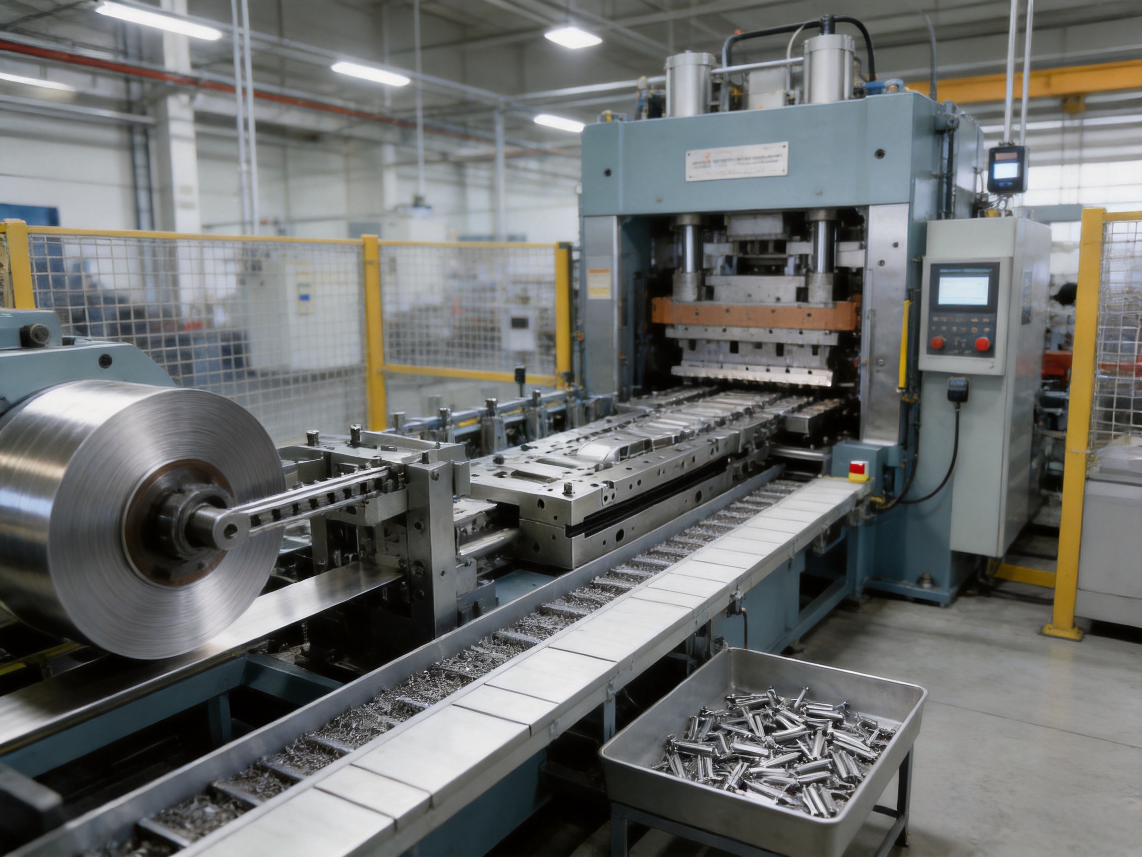
5. Scrap Evacuation and Anti-Jam Design
Scrap management is a fundamental part of progressive stamping. Small slugs, edge scrap, skeleton sections, and separated components must leave the working area reliably. If scrap accumulates inside the die, it can cause punch breakage, part deformation, strip lifting, or an unexpected machine stop.
The die incorporates optimized scrap evacuation and anti-jam features. These may include suitable discharge channels, air-assisted removal, inclined scrap paths, stripper arrangements, and clearance zones designed around the expected scrap shape. The exact configuration depends on the part geometry and the selected carrier layout.
Preventing scrap jumping is particularly important for high-speed operation. A loose slug can become trapped between the punch and die, damage a cutting edge, or mark the next component. Stable discharge paths help protect the tool and reduce unplanned downtime.
Strip warping is another risk. Narrow or heavily perforated strips may lose stiffness as material is removed. The die layout must provide sufficient support and use the carrier structure effectively until the final separation operation. Proper strip support helps prevent lifting, twisting, and inaccurate forming.
Anti-jam design also contributes to operator safety. A tool that frequently jams requires more manual intervention and increases the chance of incorrect restart procedures. Reliable automatic evacuation allows operators to monitor the process rather than repeatedly clearing scrap from the die.
6. Engineering and Customization Process
Every progressive stamping die should be designed around the actual part and production conditions. Standard tooling concepts can provide a starting point, but connector and automotive components often require a customized station layout. The manufacturer provides design and manufacturing according to customer drawings, material specifications, thickness, required stamping speed, and tolerance requirements.
6.1 Review of 2D and 3D Product Data
The process begins with a review of the customer’s two-dimensional drawings and three-dimensional models. Engineers examine critical dimensions, datums, tolerances, bend angles, holes, contact areas, surface requirements, and assembly relationships.
The review also identifies features that may affect progressive production. These include deep narrow forms, overlapping bends, small internal radii, fragile tabs, thin sections, tight hole-to-edge distances, and areas that may require special support during forming.
If the part is intended for an electrical application, contact surfaces and functional spring features receive particular attention. If it is an automotive component, the review may focus on repeatability, burr limitations, structural strength, corrosion-related requirements, and compatibility with downstream assembly.
6.2 Material and Thickness Evaluation
Material selection has a direct influence on die design. Copper alloys, brass, stainless steel, carbon steel, spring steel, aluminum, and coated materials each exhibit different cutting and forming behavior. Tensile strength, yield strength, hardness, elongation, conductivity, and surface condition all affect the process.
Material thickness determines the required clearance, punch strength, forming load, minimum radius, and strip support. Thin materials may require very fine clearances and delicate handling. Harder materials may require stronger punches, carbide inserts, special coatings, or additional forming stages.
Grain direction can also affect bending and springback. The die layout and material feeding direction may be selected to improve consistency in critical formed features. When necessary, trial results are used to refine compensation and forming conditions.
6.3 Strip Layout and Station Planning
Strip layout is one of the most important engineering decisions. The layout determines material utilization, carrier width, station pitch, part orientation, scrap volume, and the ability of the strip to remain stable throughout the process.
Engineers evaluate whether the part should be carried by side rails, center carriers, tabs, or a combination of support features. The carrier must be strong enough to transport the strip while allowing efficient material use. It must also release the completed part cleanly at the final station.
Station planning follows the natural forming sequence. Pilot holes and reference features are usually created early. Piercing and notching may occur before bending, while certain forms must be delayed until surrounding material has sufficient support. Difficult features may be divided across multiple stations to reduce force and improve accuracy.
6.4 Simulation, Machining, and Assembly
Three-dimensional design tools assist with interference checking, station verification, forming sequence analysis, and maintenance access planning. Engineers can evaluate whether punches, lifters, pilots, springs, and inserts have sufficient clearance during the press stroke.
After design approval, precision machining begins. The company is equipped with imported wire cutting machines, CNC machining centers, and more than ten grinding machines of various sizes. These resources support the manufacture of accurate die components, inserts, plates, punches, and forming elements.
Wire cutting is valuable for producing intricate profiles and narrow clearances. CNC machining supports complex three-dimensional surfaces and accurately located mounting features. Grinding is used to achieve precise flatness, thickness, parallelism, and surface finish on critical components.
Once components are manufactured, skilled technicians assemble the die and verify the relationship between the upper and lower structures. They inspect insert seating, punch alignment, guide movement, stripper function, spring force, and strip passage. Proper assembly is essential because even accurately machined components can produce poor results if they are not fitted and adjusted correctly.
6.5 Tryout and Sample Validation
Tryout is the stage where the die is tested under practical production conditions. The tool is installed on a suitable press, and the specified material is fed through the stations. Engineers observe strip movement, forming behavior, scrap discharge, part release, and press load.
Sample parts are measured against the approved drawings. Important checks may include overall dimensions, hole position, bend angle, formed height, contact geometry, burr height, surface condition, and deformation. If necessary, the tool is adjusted through insert correction, clearance refinement, forming compensation, or feed timing changes.
Tryout continues until the tool demonstrates stable operation and acceptable part quality. This stage reduces the risk that the customer will receive a die that performs well only under ideal conditions. It also provides valuable information for establishing operating parameters and maintenance recommendations.
7. Manufacturing Strengths and Integrated Production Capability
Suzhou Shuangqisi Mold Equipment Co., Ltd. is a professional manufacturer of stamping dies and hardware parts integrating design, manufacturing, and service. Its production resources include experienced technical personnel, precision machining equipment, stamping presses, assembly capability, and automation development support.
The company has approximately 60 technical staff and operates more than 25 punch presses ranging from 80 tons to 400 tons. This press range allows the organization to support different tooling sizes, material thicknesses, forming requirements, and production volumes.
The company’s equipment includes imported wire cutting machines, CNC machining centers, grinding machines of various sizes, and other precision machine tools. This in-house capability helps control the manufacturing sequence and reduces reliance on multiple external suppliers. It also supports closer coordination between design, machining, assembly, and tryout teams.
Experienced senior operators and debugging personnel contribute to practical production performance. Tooling design must be connected to real press behavior, material handling, maintenance needs, and operator procedures. Personnel with hands-on experience can identify potential problems that may not be obvious from a drawing alone.
7.1 Experience in Industrial Applications
With approximately 15 years of experience in the mold industry, the company has developed tooling and metal parts for a variety of applications. Its customers and projects include servo drive components, compressor-related parts, electrical hardware, and new energy vehicle products.
This industry experience is relevant to connector and terminal tooling because many of the same requirements apply: high repeatability, efficient production, controlled burrs, stable forming, and compatibility with automated assembly. Experience across different industries also supports the development of practical solutions for unusual part geometries and difficult materials.
7.2 Stamping Automation Equipment
In 2016, the company invested in and established Suzhou Keshuang Intelligent Technology Co., Ltd., which focuses mainly on stamping automation equipment. This expansion allows the business to support both the tooling and automation sides of a production project.
Automation may include coil feeding, straightening, transfer systems, part collection, scrap handling, inspection, counting, and production monitoring. When the die and automation equipment are developed with compatible operating conditions, the complete line can be easier to install, debug, and maintain.
The integrated capability also enables turnkey solutions. Customers may request a progressive die alone, a die and stamping production support package, or a broader system involving automation equipment and related production machinery. The company can evaluate the customer’s needs and provide a coordinated solution rather than treating the die as an isolated component.
7.3 Cost and Quality Control
Tooling cost is influenced by the number of stations, material grade, insert requirements, machining complexity, heat treatment, surface coating, tryout time, and expected service life. The lowest initial price does not always represent the lowest total cost. A tool with poor wear resistance or frequent breakdowns can create significant costs through downtime, repair, scrap, and delayed delivery.
The company emphasizes cost control together with quality control. In practical terms, this means selecting materials and structures according to the application instead of applying unnecessarily expensive solutions everywhere. Carbide is used in critical areas where it provides measurable value, while other components can be selected according to their actual loads and wear conditions.
Integrated manufacturing also helps control communication and scheduling costs. Design changes can be discussed directly with machining and assembly personnel, while tryout feedback can be returned to the engineering team quickly. This shortens the response cycle and supports efficient project execution.
8. Advantages for Connector and Terminal Production
Connectors and terminals require precision because their function depends on accurate mechanical and electrical relationships. The terminal must fit within a housing, engage with a mating terminal, maintain suitable contact pressure, and resist loosening or deformation during service.
The progressive die supports these requirements through controlled strip positioning and carefully sequenced forming. Small holes, retention lances, locking features, contact beams, crimp areas, and folded sections can be produced in a coordinated process.
Spring contacts require particular attention to forming radii, material temper, springback, and surface condition. The tool can be designed to distribute forming over several stations when necessary, reducing excessive stress and improving shape consistency.
Terminal edges must also be controlled. Excessive burrs may damage housings, reduce insertion quality, or create unreliable electrical contact. Accurate cutting clearances, carbide inserts, and regular maintenance help maintain suitable edge quality over long production runs.
For high-volume connector production, production speed is another decisive factor. The combination of high-speed die construction, continuous coil feeding, reliable pilot positioning, and effective scrap discharge supports efficient automated output.
9. Advantages for Automotive and New Energy Vehicle Components
Automotive electrical systems contain many stamped metal parts, including terminals, sensor components, grounding elements, busbar-related hardware, clips, brackets, shielding pieces, and conductive connection components. New energy vehicles add further demand for battery, power electronics, charging, and motor-related metal parts.
These applications often require consistent quality over long production periods. A progressive die designed for automotive production must withstand repeated operation while controlling burrs, deformation, wear, and dimensional variation.
The rigid four-guide-pillar structure supports reliable alignment under repeated impact. Carbide inserts increase resistance to wear in critical cutting and forming areas. Pilot pins help maintain feature location, while anti-jam structures support stable continuous production.
Automotive manufacturers also value traceability, process stability, and predictable maintenance. A modular tool makes it easier to inspect and replace specific components. A well-documented tryout process can provide recommended press settings, feed pitch, lubrication guidance, inspection points, and maintenance intervals.
For new energy vehicle parts, conductive performance and dimensional accuracy may be especially important. Components used in battery systems, power distribution, sensors, and electrical control systems must be produced consistently to support reliable assembly. The tooling can be customized for the selected copper alloy, aluminum alloy, stainless steel, or other specified material.
10. Quality, Maintenance, and Service Life
10.1 Preventive Maintenance
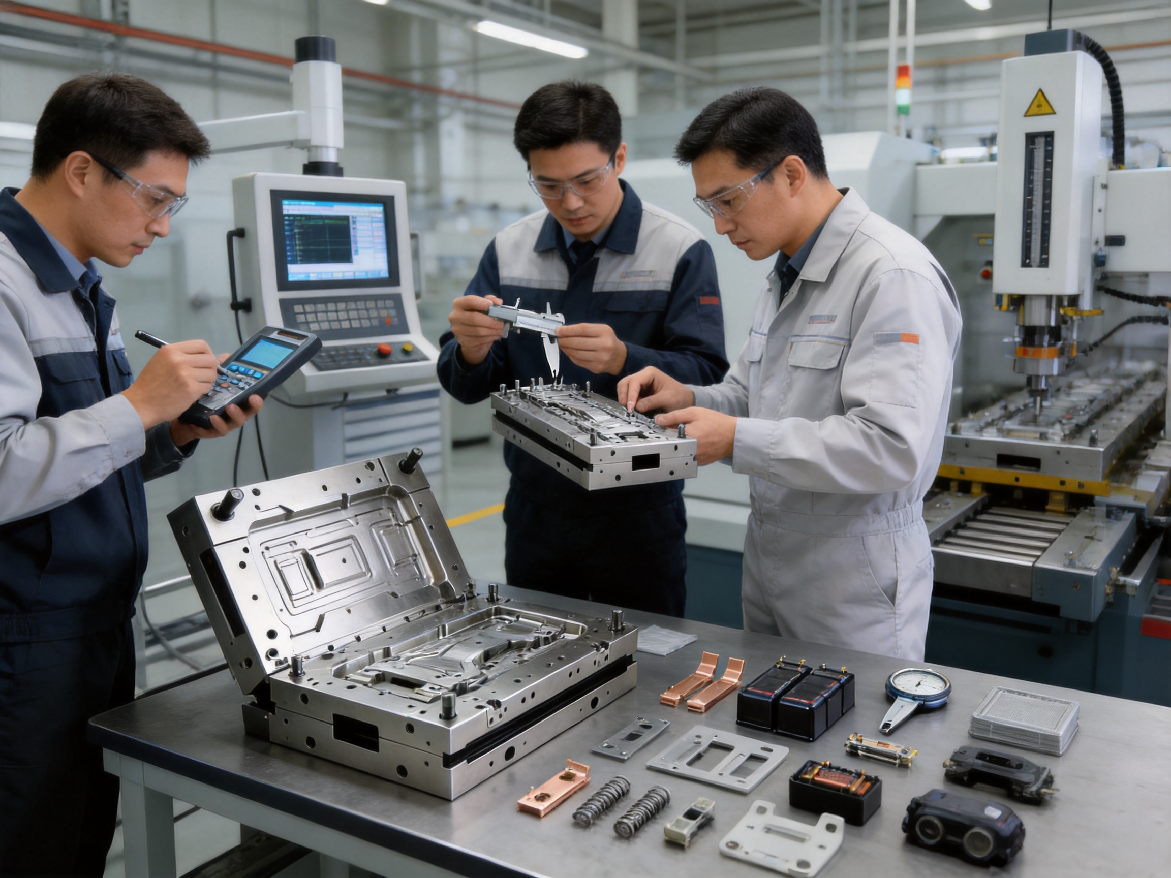
Even a high-quality progressive die requires regular maintenance. Preventive maintenance is more effective than waiting for a failure because it allows wear to be identified before it affects large quantities of parts.
Maintenance activities may include cleaning the die, checking guide pillars, inspecting pilot pins, measuring cutting edges, checking spring performance, verifying insert condition, removing accumulated material, and confirming proper lubrication. Scrap channels should be kept clear, and unusual noise or vibration should be investigated promptly.
10.2 Inspection of Wear Components
Pilot pins, punches, die inserts, forming surfaces, strippers, and guide components are typical wear items. Their inspection frequency depends on material, production speed, lubrication, part geometry, and output volume.
Small changes in punch length, cutting edge condition, or forming surface geometry may affect part quality. Establishing inspection limits helps the production team determine when an insert should be reground, replaced, or adjusted.
10.3 Lubrication and Cleanliness
Proper lubrication reduces friction between the strip and forming surfaces, supports smooth movement, and limits material pickup. The lubricant must be compatible with the material, downstream cleaning process, coating requirements, and environmental conditions.
Cleanliness is equally important. Fine particles, scrap fragments, and residue can interfere with pilot engagement, prevent a stripper from returning properly, or cause surface defects. Regular cleaning helps preserve the precision relationship between the tool components.
10.4 Monitoring Production Stability
Operators should monitor press noise, vibration, feed accuracy, strip tracking, scrap flow, part appearance, and machine load. A gradual change in any of these factors may indicate a developing problem.
For automated lines, sensors and inspection systems can assist with detecting missing parts, strip misfeeds, tool overloads, or abnormal output. Automation does not eliminate the need for maintenance, but it can provide earlier warning and reduce the risk of extended production with defective parts.
11. Why an Integrated Supplier Can Provide Greater Value
Purchasing a progressive die from a supplier that also understands stamping production and automation can provide several practical benefits. The supplier can consider not only whether the die produces an acceptable sample, but also how it will operate during continuous production.
Designers familiar with stamping presses understand the relationship between die height, press capacity, stroke, shut height, feed pitch, material width, tonnage, and production speed. Automation specialists understand how the strip feeder, straightener, scrap system, inspection devices, and part collection equipment must interact with the die.
This integrated perspective helps reduce compatibility problems. It can also simplify technical communication because the customer does not need to coordinate every detail between separate die, automation, and production suppliers.
The company’s ability to provide tooling, hardware parts, and stamping automation equipment supports turnkey project development. According to customer requirements, it may also invest in related production equipment to deliver a more complete and cost-effective solution.
12. Recommended Customer Information for a Custom Quote
To design an accurate progressive die, customers should provide as much technical information as possible. The most important documents are the latest approved 2D drawing and 3D model, if available.
Material information should include grade, thickness, temper, surface treatment, coil width, and any special conductivity or mechanical requirements. Production information should include annual volume, desired press speed, expected tool life, working shifts, and preferred automation level.
Quality information should identify critical dimensions, acceptable burr limits, visual requirements, inspection standards, and functional characteristics such as insertion force, contact pressure, or spring performance.
Customers should also provide available press specifications, including tonnage, stroke length, shut height, bolster dimensions, feed direction, maximum material width, and whether the press is equipped for high-speed progressive stamping.
Clear information at the quotation stage improves the accuracy of the die concept, station layout, cost estimate, delivery schedule, and expected production performance.
13. Typical Project Workflow
A typical project begins with technical communication and drawing review. The engineering team confirms the product requirements, material, production volume, press conditions, and quality expectations.
Next, the team develops the strip layout, station sequence, die structure, pilot system, insert strategy, scrap evacuation concept, and preliminary production parameters. The design is reviewed and refined before detailed machining data is released.
Precision components are then machined using wire cutting, CNC machining, grinding, and other suitable processes. Heat treatment and surface coating are applied where required. Components are inspected before assembly.
During assembly, technicians fit the plates, guides, punches, inserts, springs, lifters, pilots, strippers, and forming components. The complete die is checked for smooth movement and correct alignment.
Tryout follows assembly. The die is tested with the specified strip material, and samples are produced for dimensional and functional evaluation. Adjustments are made until the tool meets the agreed requirements.
After approval, the customer receives the die, samples, technical information, and relevant operating guidance. After-sales technical support is available for installation, debugging, maintenance, and production questions.
14. Questions and Answers
Q1: What is a progressive stamping die?
A progressive stamping die is a multi-station tool that performs several operations on a continuously fed metal strip. Each press stroke advances the strip and allows different stations to pierce, bend, form, emboss, trim, or blank the material. The finished part is completed after passing through the final station.
Q2: Which parts are suitable for this type of die?
The die is suitable for electronic connectors, electrical terminals, spring contacts, relay parts, power socket components, battery conductive pieces, automotive electrical hardware, sensor components, shielding sheets, brackets, and other small precision metal parts.
Q3: Can the die be customized for different materials?
Yes. The die can be designed according to the customer’s material grade, hardness, thickness, surface condition, and forming requirements. Tool clearances, insert materials, coatings, forming radii, and station sequences may be adjusted for copper alloys, stainless steel, spring materials, carbon steel, aluminum, and other strip materials.
Q4: How does the pilot pin system improve quality?
Pilot pins engage accurately prepared holes in the strip and correct the material position before critical operations. This reduces cumulative pitch error, prevents part shifting, and improves the repeatability of holes, bends, embossments, and other features during continuous production.
Q5: Why are carbide inserts used?
Carbide inserts provide high hardness and wear resistance in critical cutting and forming areas. They help maintain edge condition, reduce burr growth and material pickup, and extend service life. Because the inserts are modular, worn sections can often be replaced without rebuilding the entire die.
Q6: Can the die operate at high stamping speeds?
It is designed for stable high-speed operation when matched with a suitable press, feeder, material, lubrication system, and maintenance program. The rigid four-guide-pillar structure, accurate pilot positioning, carbide inserts, and scrap evacuation system support high-speed production.
Q7: How does the modular design help maintenance?
The modular structure allows technicians to remove, inspect, adjust, or replace individual inserts and working sections. This reduces repair time and production downtime compared with a tool in which all working elements are permanently integrated into large, difficult-to-service blocks.
Q8: Can the supplier provide stamping automation equipment?
Yes. The associated automation capability covers stamping automation equipment and can support coil feeding, straightening, scrap handling, part collection, inspection, and other production-line functions. Tooling and automation can be developed as a coordinated solution.
Q9: What information is needed for a quotation?
The supplier normally needs product drawings or models, material grade and thickness, annual quantity, desired production speed, critical tolerances, burr requirements, available press specifications, and the preferred automation level. Functional requirements and sample expectations should also be provided.
Q10: What industries can benefit from this tooling?
The main application areas include electronics, electrical equipment, automotive manufacturing, electric vehicles, new energy systems, battery components, sensors, consumer electronics, compressors, servo drives, and general precision hardware production.
15. Conclusion
A high-speed progressive stamping die is an important production asset for manufacturers of connectors, terminals, electrical hardware, automotive components, and other precision metal parts. By integrating multiple operations into one continuous tool, it improves efficiency, reduces handling, supports automated production, and provides consistent part quality.
The product’s main technical advantages include high-hardness pilot pin positioning, carbide inserts, professional surface coatings, a rigid four-guide-pillar structure, modular working sections, comprehensive multi-station forming capability, and optimized scrap evacuation. Together, these features support high-speed operation, long service life, low defect rates, and easier maintenance.
The manufacturing strength behind the product is equally important. Suzhou Shuangqisi Mold Equipment Co., Ltd. combines design, precision machining, assembly, tryout, stamping production experience, hardware manufacturing, and automation equipment development. Its technical staff, precision equipment, press capacity, industrial experience, and integrated service model allow it to support projects from initial concept through production implementation.
For customers seeking a reliable custom stamping die, the greatest value comes from matching the tool structure to the actual product, material, press, and production target. A carefully engineered progressive die can provide not only high output, but also lower total production cost, more stable quality, reduced downtime, and a stronger foundation for automated manufacturing.
References
1. Metal Forming Handbook, principles of sheet metal cutting, bending, forming, and progressive die design.
2. Tool and Manufacturing Engineers Handbook, guidance on stamping tool materials, die construction, press selection, and production control.
3. Fundamentals of Modern Manufacturing, analysis of sheet metal processes and automated production systems.
4. Recommended Practices for the Design and Maintenance of Progressive Dies, technical guidance on pilot systems, die alignment, wear control, and scrap management.
5. General engineering principles for carbide tooling, surface coatings, high-speed stamping, and precision metal component production.
6. Technical information supplied for the custom progressive stamping die for connector, terminal, automotive, and electrical hardware applications.
Product: Progressive Stamping Die for Connector & Terminal Parts High Speed Progressive Stamping Die Precision Metal Hardware Stamping Tool mold for Connector Terminal Parts Automotive Components
Previous Post
Deep Drawing Dies for Front and Rear Wheels of Two-Wheeled Electric Vehicles
Next Post
Precision Progressive Molds for Automotive Motor Housings and Small Parts
Our Products.
Start Your Business with an OEM Manufacturer Right Here!

Provide global customers with complete turn-key solutions
through
innovation!
QUICK LINKS
CONTACT INFO.
-
 +86-139 1308 8972
-

-
 No. 118 Yexin Road, Wujiang Economic Development Zone, Suzhou, China
Copyright © Suzhou Shuangqisi Mold Equipment Co., Ltd. All Rights Reserved. Custom Stamping Die Metal Stamping Die Manufacturers
