 English
 Español
 Deutsch

-
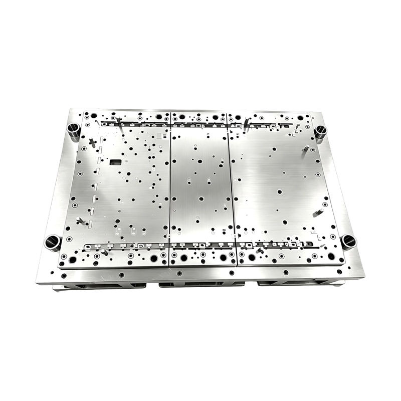
High Precision Stamping Die Multi Station Hardware Progressive Mold Tooling
Precision Metal Stamping Tool for Automotive &...
-
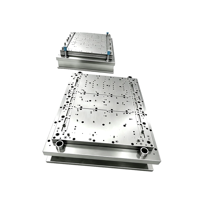
Progressive Stamping Die for Connector & Terminal Parts High Speed Progressive Stamping Die Precision Metal Hardware Stamping Tool mold for Connector Terminal Parts Automotive Components
Progressive Stamping Die for Connector & Termi...
-
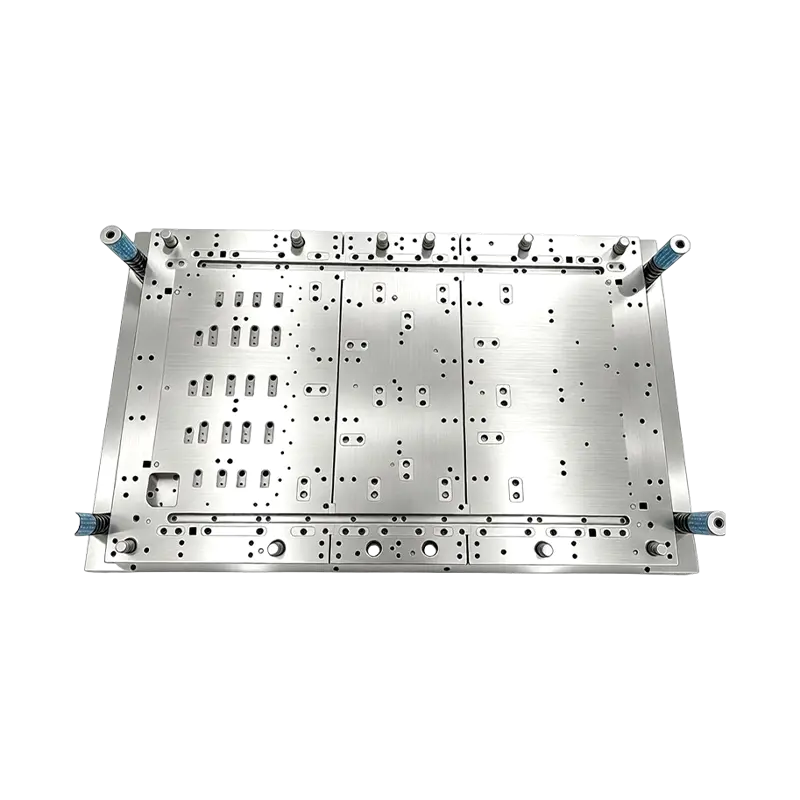
Multi-Station Progressive Stamping Die with Carbide Inserts Custom Multi Station Progressive Stamping Die Carbide Insert Metal Stamping Mold Tool for Equipment Appliances Device Hardware
High Speed Metal Stamping Tool for Precise Equipme...
-
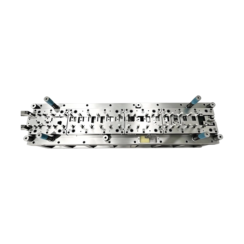
Long-Stroke Multi-Stage Progressive Die Automatic Strip Feed Progressive Die Long Travel Follow on Stamping Tool for Sheet Metal Hardware Press Moulding
Long-Stroke Multi-Stage Progressive DieOur custom ...
-
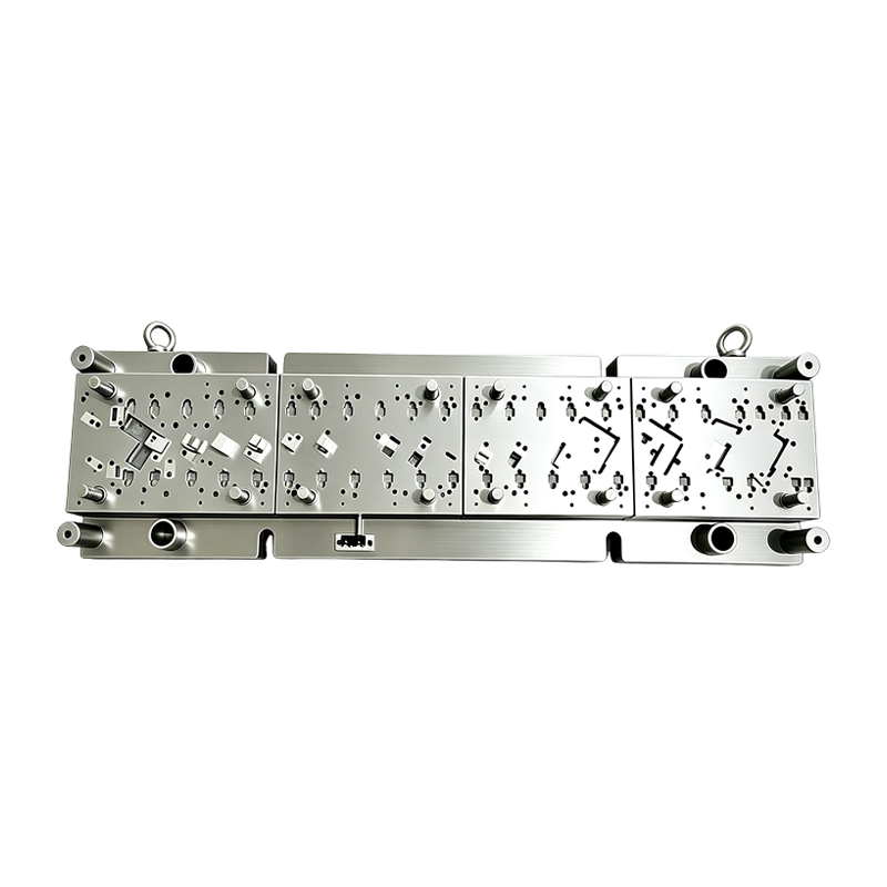
High Speed Progressive Stamping Die Sheet Metal Follow on Press Tool
Multi-operation Metal Stamping Tool for Continuous...
-
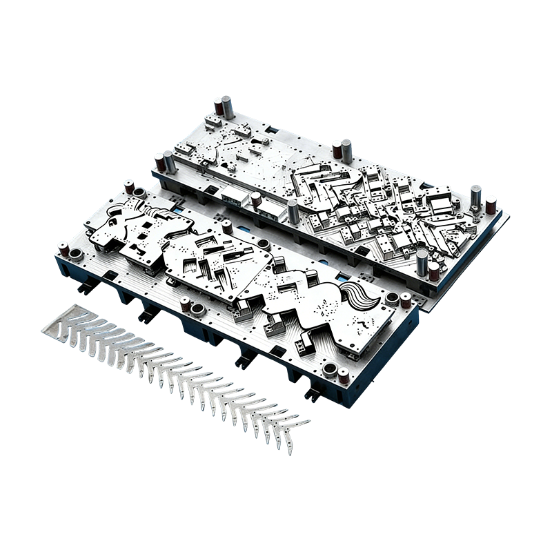
Progressive molds for automotive parts
This Continuous mold for automotive motor housing ...
- E-mail us: [email protected]
- Call us: +86-139 1308 8972

Chen Siyi – Overseas Sales Manager
Home / Author / Chen Siyi – Overseas Sales Manager / High-Precision Multi-Station Progressive Stamping Dies for Automotive, Electronics, and New Energy Manufacturing
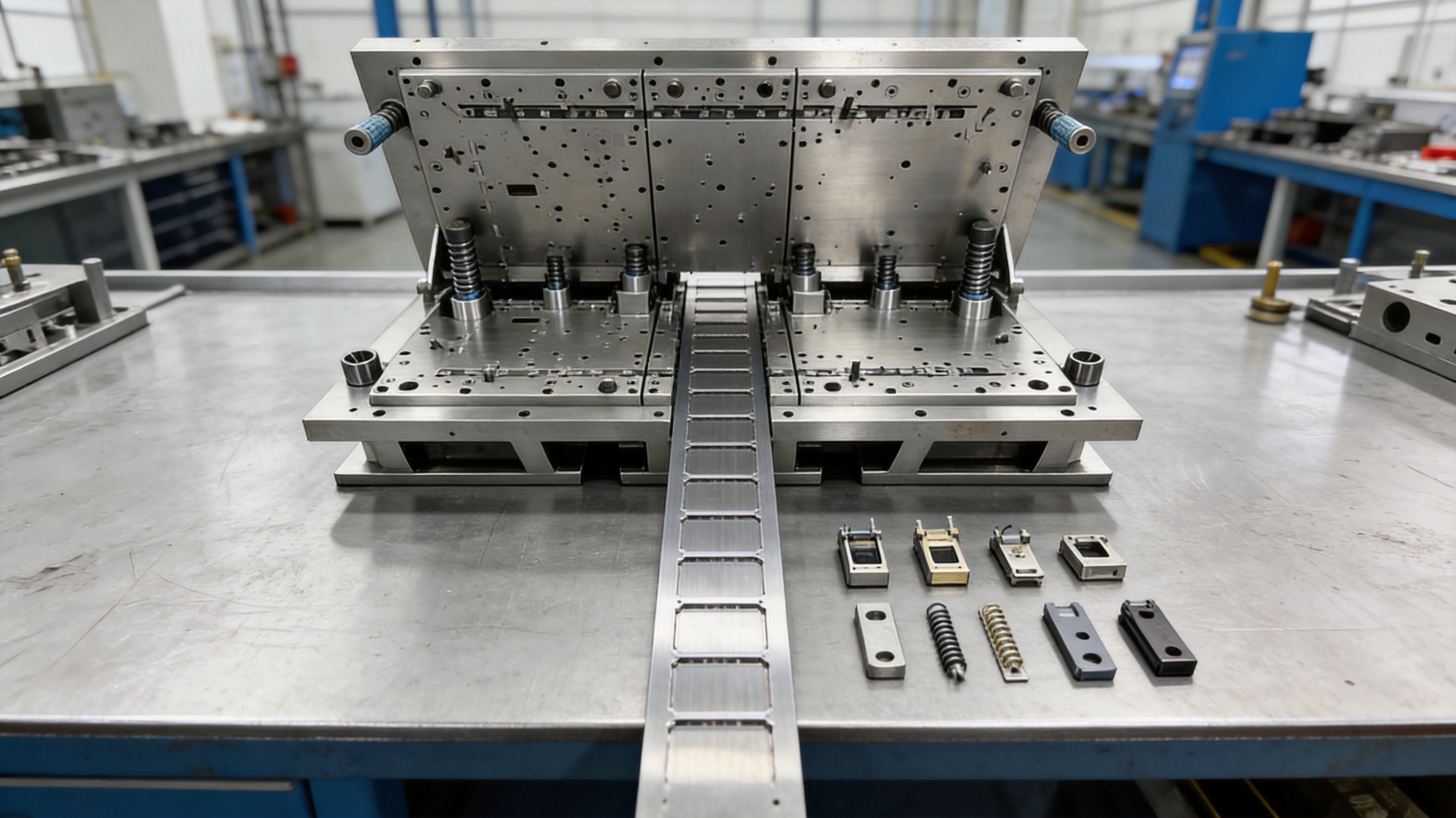
High-Precision Multi-Station Progressive Stamping Dies for Automotive, Electronics, and New Energy Manufacturing
2026-11-07
In high-volume metal component production, the stamping die is one of the most important factors affecting productivity, dimensional consistency, material utilization, and long-term manufacturing cost. A well-designed die does more than cut or form metal. It coordinates material feeding, piercing, blanking, bending, drawing, forming, and part separation in a controlled sequence while maintaining repeatable accuracy over thousands or millions of press cycles.
The high-precision multi-station progressive stamping die described in this article is developed for continuous production of thin and medium-gauge metal parts used in automotive systems, electric vehicles, consumer electronics, home appliances, telecommunications equipment, and other precision industries. By integrating multiple independent working stations into one die set, the tooling allows strip material to move through a series of operations during each press stroke. This arrangement can significantly reduce manual handling, support high output, and provide a stable process for demanding mass-production programs.
Designed and manufactured by Suzhou Shuangqisi Mold Equipment Co., Ltd., the tooling combines precision die construction, modular components, advanced machining, engineering analysis, tryout, and stamping automation capabilities. The result is a customized production solution rather than a standard off-the-shelf mold. Each die can be developed according to the customer’s component drawing, material characteristics, production volume, press conditions, tolerance requirements, and downstream assembly needs.
High Precision Stamping Die Multi Station Hardware Progressive Mold Tooling
Content
- 1 What Is a Multi-Station Progressive Stamping Die?
- 2 Core Product Advantages
- 3 Engineering and Design Process
- 4 Advanced Manufacturing Capabilities
- 5 Tryout, Inspection, and Pre-Shipment Validation
- 6 Why Integrated Die and Automation Capability Matters
- 7 Company Manufacturing Strengths
- 8 Comparison With Conventional Multi-Tool Production
- 9 Maintenance Recommendations
- 10 Ordering and Customization Considerations
- 11 Quality and Production Value
- 12 Questions and Answers
- 12.1 What types of parts are suitable for this progressive stamping die?
- 12.2 Can the die perform both cutting and forming operations?
- 12.3 Is the tooling suitable for electric vehicle and new energy components?
- 12.4 How does modular insert construction reduce maintenance cost?
- 12.5 What surface treatments are available?
- 12.6 How is dimensional accuracy verified before shipment?
- 12.7 Can the supplier provide automation equipment as well as the die?
- 12.8 What press sizes can be supported?
- 12.9 How long can the die operate before maintenance is required?
- 12.10 What information should be provided for a quotation?
- 13 Conclusion
- 14 References
- 15 Product: High Precision Stamping Die Multi Station Hardware Progressive Mold Tooling
What Is a Multi-Station Progressive Stamping Die?
A progressive stamping die is a precision tool that performs several operations on a continuously fed strip of metal. The strip enters the die through a controlled feeding system and advances by a defined pitch after each press stroke. At every station, a specific operation is completed. One station may pierce holes, another may cut an external profile, another may bend a tab, and later stations may form, draw, coin, or separate the finished part.
Unlike a single-operation die, which usually requires a separate tool for each manufacturing step, a progressive die combines many operations into one integrated structure. This makes it particularly suitable for high-volume production where stable cycle time, low labor content, repeatable quality, and automated material handling are essential.
The term “multi-station” refers to the number and arrangement of working positions within the die. The precise layout depends on the geometry of the workpiece. A relatively simple electrical terminal may require piercing, trimming, bending, and cutoff stations. A more complex automotive or new energy component may require a combination of pilot piercing, carrier design, blanking, embossing, lancing, deep forming, bending, coining, and final separation.
Progressive tooling can also be configured for parts that include deep-drawing or controlled forming characteristics. The final design must be evaluated through a detailed engineering process because deep drawing, material flow, springback, wall thinning, lubrication, and forming force can influence the number of stations and the required die structure.
Sequential Production Within One Die Set
During operation, a coil or pre-cut strip is fed into the die. The feeding system advances the material by a carefully controlled distance. The press then drives the upper die downward, allowing each station to perform its designated task. When the press returns, the strip advances again, and every partially processed part moves to the next station.
After the initial lead-in period, a finished component can be produced during every press cycle. This continuous sequence is one of the main reasons progressive dies are preferred for large-volume production. It eliminates the need to transfer semi-finished parts manually between several independent tools and reduces the number of handling steps that can introduce errors or surface damage.
Typical Operations Integrated Into the Tool
Depending on the workpiece, a customized die may integrate piercing, blanking, trimming, bending, forming, embossing, lancing, coining, drawing, and cutoff operations. The order of these operations is determined by material behavior, part geometry, press capacity, required tolerances, and the desired production rate.
Piercing stations create holes or slots before later forming operations make access more difficult. Blanking stations establish the external contour or separate a part from the strip. Bending stations create tabs, flanges, or angled features. Forming stations produce ribs, bosses, contact surfaces, or three-dimensional profiles. Drawing stations move material into a cavity to create a deeper shape, while coining stations improve local definition and dimensional precision.
The die may also use a carrier or skeleton layout to maintain strip stability as the material travels through the tool. Proper carrier design is particularly important when the workpiece contains narrow sections, long unsupported areas, or several forming operations that could otherwise distort the strip.
Core Product Advantages
The principal advantage of this tooling is the integration of several production processes into one accurately controlled system. However, its value extends beyond simply combining operations. The tooling architecture, guide system, insert strategy, surface treatment options, engineering workflow, and validation procedures all influence the customer’s total manufacturing result.
High Production Efficiency
A multi-station progressive die can produce parts continuously with limited operator intervention. Once the coil feeding, press settings, lubrication, sensors, and safety systems have been properly configured, the production line can operate at a repeatable cycle rate. This helps manufacturers achieve high output without assigning workers to transfer components between separate presses.
The integrated layout can reduce work-in-process inventory and shorten the distance that material travels through the factory. It can also simplify production planning because several operations are managed within one tooling system rather than distributed across multiple independent processes.
For automotive electronics terminals, battery contact components, sensor brackets, spring contacts, connector pins, and similar parts, the ability to produce one finished component per press stroke can provide a meaningful productivity advantage. The actual output depends on the press speed, material thickness, part pitch, die design, inspection requirements, and the number of cavities or lanes, but the progressive principle supports a highly efficient production model.
Consistent Dimensional Accuracy
Precision parts often contain small holes, narrow slots, formed tabs, contact surfaces, or mating features that must remain within controlled tolerances. The die’s guide pin and guide plate system helps maintain alignment between the upper and lower assemblies during repeated press movement. Accurate guidance reduces lateral movement and supports stable interaction between punches, inserts, stripper components, and die openings.
Consistent strip feeding is equally important. If the material advances too far or not far enough, every subsequent operation can be affected. A carefully designed pitch-control system, combined with pilot pins and reliable feeding equipment, helps position the strip accurately at each station. This can reduce part-to-part variation, minimize progressive accumulation of error, and improve the repeatability of critical dimensions.
Dimensional performance is also supported by the quality of the die components. Precision CNC machining, wire cutting, grinding, inspection, and controlled assembly help create the close-fitting relationships required for a high-performance stamping tool.
Lower Scrap and Reduced Manual Handling
One integrated progressive tool can eliminate several manual transfer steps. Every time a component is picked up, repositioned, or placed into another tool, there is a possibility of incorrect orientation, deformation, contamination, or accidental surface damage. Continuous strip processing reduces many of these risks.
Material utilization can also be considered during the early layout stage. The strip width, pitch, carrier structure, and nesting arrangement are optimized according to the part geometry and material width. A suitable layout can reduce unnecessary skeleton waste while preserving sufficient support for accurate feeding and safe forming.
Reducing scrap is not only an environmental objective. It directly affects the cost of raw material, press time, sorting, recycling, and quality control. For copper alloys, stainless steel, high-strength steel, aluminum, and other materials with significant purchase costs, an efficient strip layout can produce meaningful savings over a long production program.
Modular Insert Construction
The die can use a modular insert structure in areas exposed to repeated cutting, forming, or impact. When an individual cutting insert becomes worn or damaged, it may be replaced separately instead of requiring the entire die block to be remanufactured. This approach can shorten maintenance time and reduce repair expense.
Modular construction also supports design flexibility. Wear-prone areas can be made from specialized materials, while other regions can use a different grade optimized for toughness, machinability, or cost. If a customer later changes a hole size, edge profile, or local forming feature, a replaceable insert may offer a practical route for modification, subject to engineering review.
For production environments where press downtime is expensive, serviceable components are a major advantage. Maintenance teams can inspect wear areas, replace individual elements, restore clearances, and return the die to operation more efficiently than with a fully monolithic construction.
Wear Resistance and Extended Service Life
Progressive dies operate under repeated mechanical and abrasive stress. Cutting edges are exposed to impact and friction, while forming surfaces experience sliding contact and pressure. The choice of die steel, heat treatment, surface finish, lubrication, and coating has a direct effect on service life.
The tooling can be specified with surface treatment options such as TD coating and PVD coating, depending on the application. These treatments can improve surface hardness, reduce friction, increase resistance to adhesive wear, and protect selected components from premature degradation. The correct treatment depends on material type, forming operation, production volume, required surface finish, and the operating environment.
Coating is not a substitute for sound die design. It works most effectively when combined with suitable clearances, stable guiding, correct lubrication, adequate support, and appropriate base material. A complete engineering evaluation is therefore needed before selecting a coating system.
Adaptability to Multiple Industries
The same progressive tooling principle can support a wide variety of industries, even though each die is customized for a particular component. Automotive and electric vehicle programs may require terminals, brackets, sensor components, motor sheet metal parts, busbar hardware, or battery contact elements. Electronics manufacturers may need shielding parts, spring contacts, connector pins, and conductive components.
Home appliance and telecommunications applications may involve thin structural brackets, switch components, internal supports, or small formed metal parts. The common requirements are high repeatability, controlled geometry, efficient material use, and reliable production over an extended service period.
| Application Sector | Representative Components | Typical Tooling Requirements | Primary Production Objectives |
|---|---|---|---|
| New energy and electric vehicles | Battery contact parts, busbar hardware, motor sheet metal components | High repeatability, controlled forming, wear-resistant inserts, stable feeding | High output, electrical and dimensional reliability, low scrap |
| Automotive | Sensor parts, electronic terminals, small brackets | Precise piercing, bending, forming, and inspection capability | Consistent assembly fit, automated production, long service life |
| Consumer electronics | Shielding shells, spring contacts, connector pins | Fine features, controlled clearances, clean surface finish | Miniaturization, repeatability, high-volume production |
| Home appliances | Internal brackets and conductive switch components | Flexible station design and economical maintenance | Stable quality and competitive manufacturing cost |
| Telecommunications | Thin structural parts for communication modules | Accurate profiles, thin-material handling, controlled flatness | Reliable fit, efficient production, reduced variation |
Engineering and Design Process
The quality of a stamping die is determined long before steel is cut. A successful project begins with a clear understanding of the part, the material, the production target, the available press, and the customer’s quality requirements. The engineering team can then develop a tool structure that balances output, precision, durability, maintenance, and manufacturing cost.
Review of Customer Drawings
The first stage is a review of the customer’s two-dimensional drawings, three-dimensional models, material specifications, tolerances, surface requirements, and inspection standards. Critical dimensions are identified, including hole position, edge profile, flatness, bend angle, formed height, contact area, and assembly-related features.
The engineering review also examines whether the proposed part geometry is suitable for progressive production. Some features may need to be adjusted to improve material flow, prevent tearing, create adequate support, or allow reliable punch and insert access. Any proposed design-for-manufacturing change should be reviewed with the customer before tool construction begins.
DFM Analysis and Strip Layout
Design for manufacturability analysis is used to determine the most practical operation sequence. Engineers consider the direction of material flow, station spacing, carrier structure, pilot locations, cutting clearances, forming progression, scrap removal, and final part separation.
The strip layout is one of the most important design documents in a progressive die project. It shows how the raw material moves through the stations and how much material is used to carry the workpiece. A good layout provides enough support for reliable feeding while avoiding unnecessary waste. It also distributes forming forces in a way that helps maintain die stability.
For parts involving drawing or complex forming, the layout must account for the amount of material needed to form the shape without excessive thinning or wrinkling. Intermediate forming stages may be required rather than attempting to create the final geometry in one operation.
Press and Material Evaluation
The die must be matched to the press that will operate it. Important press parameters include nominal tonnage, working energy, stroke length, shut height, slide dimensions, bolster dimensions, feed direction, speed range, and available automation interfaces.
Material evaluation includes thickness, tensile strength, yield strength, hardness, elongation, surface condition, coil width, and edge quality. Copper and aluminum alloys may have different cutting and forming behavior from stainless steel or high-strength steel. Material properties influence punch strength, die clearance, springback, lubrication, forming radius, and expected tool wear.
Press capacity should include an appropriate safety margin. A tool that operates close to the maximum press rating may experience instability, excessive vibration, or accelerated wear. The forming load should be distributed across the die whenever possible, and the tooling should be designed for the actual production conditions rather than only the nominal part shape.
Three-Dimensional Tool Design
After the strip layout and process sequence are approved, the die structure is developed in three-dimensional CAD software. The assembly may include upper and lower die plates, guide posts, guide bushes, punches, die inserts, stripper plates, pressure pads, pilots, springs, lifters, sensors, scrap chutes, and material support components.
Clearances are carefully established between punches and die openings. Incorrect clearance can create excessive burrs, poor edge quality, high cutting force, or premature tool failure. Forming surfaces are designed to control material movement and avoid interference between adjacent stations.
Maintenance access is also considered during the design phase. Wear components should be accessible for inspection and replacement. The die should include suitable methods for disassembly, alignment, adjustment, and safe lifting. A tool that performs well but is difficult to maintain can create unnecessary long-term cost, so serviceability is an important part of the overall design.
Simulation and Risk Reduction
Where appropriate, forming simulation and engineering verification can be used to evaluate material flow, possible thinning, wrinkling, springback, collision, and forming load. Simulation does not replace physical tryout, but it can help identify risks before the die is manufactured.
Potential issues are reviewed at the design stage. Examples include insufficient carrier strength, interference between a punch and a formed feature, inadequate scrap clearance, excessive bending stress, or an operation sequence that makes a later feature difficult to control. Early correction is generally less expensive than modifying a completed die.
Advanced Manufacturing Capabilities
Suzhou Shuangqisi Mold Equipment Co., Ltd. provides integrated die design, manufacturing, debugging, and service. Its production resources include imported wire cutting machines, CNC machining centers, more than ten grinding machines of different sizes, and punch presses ranging from 80 tons to 400 tons.
This combination of equipment supports the principal stages of precision die production. CNC machining centers are used for accurately machining die plates, cavities, pockets, and structural components. Wire cutting equipment is suitable for fine profiles, narrow slots, precision openings, and hardened components that require controlled geometry. Grinding machines support flatness, parallelism, surface finish, and close dimensional control.
The availability of multiple grinding machines allows different component sizes and configurations to be processed according to their requirements. Grinding is especially important for die components that must maintain accurate mating surfaces, consistent thickness, or controlled edge conditions.
Precision CNC Machining
CNC machining provides repeatable production of complex three-dimensional surfaces and accurately located mounting features. Tooling components can be machined from digital design data, reducing manual layout work and supporting consistency between replacement inserts and original components.
Machining strategy is selected according to the material, feature geometry, required tolerance, and surface finish. Rough machining removes bulk material efficiently, while finishing operations create the final form. Critical components may receive additional grinding or wire-cutting operations after heat treatment to restore the required dimensions.
Wire Cutting
Wire EDM is often used for fine die openings, precision inserts, punch profiles, and hardened steel components. It can produce intricate contours that would be difficult to machine by conventional cutting methods. The process is useful for small holes, narrow slots, sharp transitions, and complex two-dimensional profiles.
Wire-cut components must still be integrated into a complete die system with suitable support, clearance, and alignment. Precision at the individual component level is valuable only when the complete assembly is properly matched and adjusted.
Grinding and Surface Finishing
Grinding contributes to the dimensional stability and functional precision of the die. Flat die plates, backing components, inserts, and guide-related surfaces may require carefully controlled grinding. Surface finish can influence friction, material flow, wear, and the quality of stamped edges or formed surfaces.
Different areas of the die may require different surface conditions. Cutting edges need sharp, accurately defined profiles. Forming surfaces may require smooth transitions to reduce marking or galling. Sliding components need suitable finish and lubrication compatibility. These details are addressed according to the specific part and material.
Heat Treatment and Material Selection
Die steel selection is based on the expected loading, wear conditions, material being stamped, production quantity, and required maintenance interval. Cutting punches may require high compressive strength and wear resistance, while certain structural components may benefit from greater toughness.
Heat treatment helps develop the mechanical properties required for service. The heat-treatment process must be controlled to limit distortion and maintain the dimensional relationships needed during final finishing. After heat treatment, critical parts may be ground or wire cut to achieve the final size and profile.
Experienced Assembly and Debugging
A precision die is not completed when all components have been machined. Skilled assembly is required to fit the components, check movement, confirm clearances, install springs and guides, verify strip travel, and ensure that the die opens and closes safely.
Experienced debugging personnel are particularly important during tryout. They can identify whether a problem comes from feeding, alignment, clearance, material condition, press settings, lubrication, forming sequence, or component adjustment. Their practical experience helps convert design intent into stable production performance.
Tryout, Inspection, and Pre-Shipment Validation
Before delivery, the die undergoes trial production and inspection. Tryout allows the engineering team to evaluate actual stamping behavior using the customer’s specified or approved material. The process can reveal burrs, forming marks, springback, feeding instability, incomplete separation, or dimensional drift.
Die Tryout
During tryout, the die is installed on a suitable press and operated through progressive stages. Initial strokes may be performed slowly to verify movement and station interaction. The team then adjusts feeding, pressure, lubrication, timing, and other process parameters before increasing production speed.
Trial parts are collected from different stages of the run. This helps determine whether dimensions remain stable after the die reaches operating conditions. It also allows engineers to inspect the condition of the strip, scrap, cutting edges, and formed surfaces.
Dimensional Inspection
Inspection focuses on the dimensions identified as critical in the customer’s drawings. Depending on the part, this may include hole diameter, hole position, profile, bend angle, formed height, flatness, burr direction, material thickness, and surface condition.
Inspection equipment and methods are selected according to the component’s size and tolerance. Results can be recorded in an inspection report for customer review. When a part has multiple critical features, a structured inspection plan helps ensure that the entire component is evaluated rather than only a few easily measured dimensions.
Stamped Samples
Stamped samples are supplied for customer confirmation. These parts allow the customer to assess fit, function, assembly, surface condition, and compatibility with subsequent processes. If the part will be assembled with plastic, electronic, battery, or automotive components, sample evaluation can include functional tests beyond simple dimensional inspection.
Customer feedback from the sample stage can lead to final adjustments. These may involve small changes to forming height, bend angle, burr control, cutoff location, or surface treatment. Confirming the sample before shipment helps reduce the risk of unexpected issues at the customer’s production site.
Documentation and Handover
A professional tooling handover may include die drawings, station layouts, inspection records, sample approvals, maintenance guidance, spare-parts information, and recommended operating parameters. Clear documentation supports production startup and helps the customer’s maintenance team understand the tool’s service requirements.
Instructions may cover lubrication, cleaning, inspection frequency, insert replacement, guide component care, punch sharpening, and safe handling. Regular preventive maintenance is essential for preserving accuracy and extending die life.
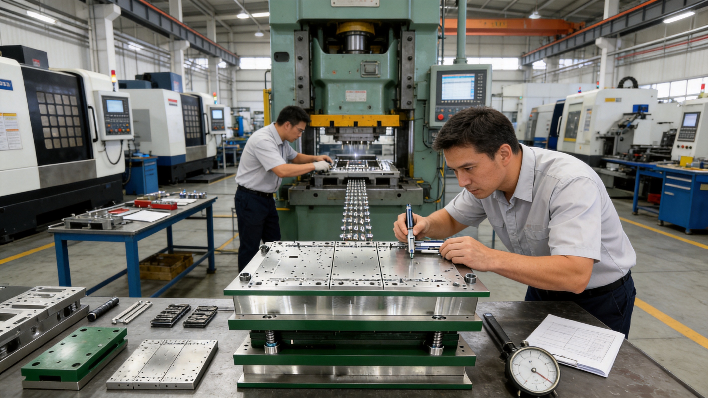
Why Integrated Die and Automation Capability Matters
Stamping dies operate most effectively when they are matched to reliable feeding and automation equipment. Suzhou Shuangqisi Mold Equipment Co., Ltd. also has an associated investment in Suzhou Keshuang Intelligent Technology Co., Ltd., which focuses on stamping automation equipment. This creates an opportunity to coordinate tooling and automation requirements rather than treating them as completely separate projects.
An integrated approach can address coil feeding, straightening, transfer, part collection, scrap removal, sensor integration, and production monitoring. It can also help ensure that the die’s pitch, feed height, press interface, and material-handling requirements are compatible with the proposed automation system.
For customers seeking a turnkey solution, the combination of die manufacturing and stamping automation can simplify project coordination. Instead of managing multiple suppliers with different technical assumptions, the customer can work with a team capable of considering the die, press, feeding system, and production workflow together.
Automation may also support improved workplace safety by reducing manual access to the die area. Sensors, interlocks, monitoring systems, and controlled material handling can help create a more consistent production environment when properly engineered and operated according to applicable safety requirements.
Company Manufacturing Strengths
Suzhou Shuangqisi Mold Equipment Co., Ltd. is located in Suzhou, China, and focuses on stamping dies, stamped hardware parts, and stamping automation equipment. The company has approximately 60 technical staff and more than 15 years of experience in the mold industry.
Its manufacturing resources include precision machining equipment, grinding capacity, wire cutting, and a group of punch presses ranging from 80 tons to 400 tons. This equipment base enables the company to support different die sizes, materials, and production requirements.
The company serves customers in fields including servo drives, compressors, automotive systems, and new energy vehicles. Its reported client base includes Anter Group, Ousheng Electric, Dongbei Group, and Huichuan Technology. These industry applications require dependable tooling, controlled cost, and stable production support.
A further strength is the combination of design, production, debugging, and service within one organization. This integrated model can improve communication between engineering and manufacturing teams. Design decisions can be reviewed against actual machining capability, and production feedback can be incorporated into later projects.
The company’s stated approach emphasizes technical expertise, cost control, quality management, and long-term customer value. For custom tooling, these factors are important because the lowest initial purchase price does not always represent the lowest total cost. A die that is difficult to maintain, frequently requires adjustment, or produces unstable parts can create much greater expenses during production.
Experienced Technical and Operating Personnel
Senior operators and experienced debugging personnel contribute practical knowledge that cannot be obtained from drawings alone. They understand how material behaves during feeding, how a press responds under load, how cutting edges wear, and how small adjustments can affect final part quality.
This experience is useful during the transition from design to tryout. It also supports troubleshooting when the customer changes material, increases production speed, introduces a different lubricant, or modifies a downstream assembly requirement.
Competitive Cost Through Process Integration
Cost competitiveness is supported by integrated production resources, in-house technical personnel, and the ability to coordinate die manufacturing with stamping automation. When engineering, machining, assembly, and debugging are managed efficiently, unnecessary delays and communication gaps can be reduced.
Modular inserts, replaceable wear parts, and structured maintenance planning can further reduce the lifetime cost of the tooling. The most economical die is not necessarily the one with the lowest purchase quotation. It is the one that provides suitable output, acceptable scrap, manageable maintenance, and dependable performance throughout the production program.
Comparison With Conventional Multi-Tool Production
In a conventional production arrangement, a part may pass through several separate dies installed on different presses. Each process requires its own setup, handling, inspection, and material transfer. This approach can be suitable for low-volume production, large parts, or operations that cannot be integrated into a progressive tool.
However, for small and medium-sized precision components, a multi-station progressive die can offer several important benefits. It can reduce the number of setups, shorten handling time, improve process continuity, and make automated production easier. The same strip remains controlled as it passes through the stations, which can support better alignment between operations.
A progressive die also creates a more centralized maintenance responsibility. Instead of maintaining many separate tools, the customer manages one integrated die set with replaceable wear components. This can simplify spare-parts planning, although the progressive tool itself may be more complex and requires disciplined maintenance.
| Evaluation Factor | Progressive Multi-Station Die | Several Separate Dies |
|---|---|---|
| Material handling | Continuous strip movement with limited manual transfer | More transfer and repositioning between operations |
| Production speed | Suitable for continuous high-volume cycles | Depends on the speed and coordination of each separate process |
| Process integration | Piercing, blanking, bending, forming, and cutoff can be combined | Each operation is usually performed in a separate setup |
| Floor-space demand | Can reduce the number of presses and handling stations | May require several presses, operators, and staging areas |
| Maintenance | Centralized but technically more complex | Distributed across multiple simpler tools |
| Best application | Stable, high-volume production of repeatable parts | Low-volume, variable, large, or difficult-to-integrate components |
The correct choice depends on the component and production plan. Progressive tooling is most advantageous when demand is high, the material can be fed continuously, and the part geometry allows the operations to be arranged safely and economically within one die.
Maintenance Recommendations
Regular maintenance is essential for preserving precision and avoiding unplanned downtime. The maintenance schedule should be based on production volume, material type, press speed, die construction, coating, and observed wear.
Operators should inspect cutting edges, forming surfaces, pilots, guide components, springs, stripper plates, and inserts at defined intervals. Burr growth, unusual noise, increased press load, feeding errors, part deformation, and surface marks may indicate that a component requires adjustment or replacement.
Cleaning is also important. Scrap particles, stamping oil residue, and metal dust can accumulate around moving components or interfere with accurate seating. The die should be cleaned using methods compatible with its materials and surface treatments.
Lubrication must be applied according to the tooling and material requirements. Excessive lubrication can contaminate parts or interfere with downstream processes, while insufficient lubrication can increase friction, galling, forming force, and wear. The correct lubricant and application method should be confirmed during tryout.
When an insert or punch reaches its service limit, it should be replaced or reconditioned before secondary damage occurs. Continuing to operate with a worn cutting edge may affect part quality and place additional stress on neighboring components. Modular construction makes this preventive approach more practical and economical.
Ordering and Customization Considerations
Customers planning a new progressive die project should provide complete technical information at the beginning of the quotation and design process. Useful information includes part drawings, three-dimensional models, material grade, thickness, annual volume, target cycle rate, allowable burr, critical tolerances, surface requirements, press specifications, coil dimensions, and inspection standards.
It is also helpful to identify whether the die will be used for prototype production, medium-volume production, or long-term mass production. The expected production volume influences the selection of die steel, coating, spare components, station arrangement, and maintenance strategy.
Customers should explain any downstream requirements, such as welding, riveting, plating, heat treatment, electrical contact, plastic molding, or automated assembly. These processes may influence the allowable surface condition, burr direction, material hardness, and dimensional control of the stamped part.
Questions about tool life, recommended spare parts, tryout samples, delivery conditions, automation interfaces, and technical documentation should be addressed before final approval. A clear specification helps ensure that both supplier and customer share the same expectations.
Quality and Production Value
The value of a high-precision progressive stamping die can be measured through several related outcomes: part consistency, output rate, scrap percentage, labor requirements, tool maintenance, changeover time, and production continuity. Improving one factor may influence the others, so the die must be evaluated as part of the complete manufacturing system.
For example, a faster cycle rate is not beneficial if it creates excessive burrs or unstable feeding. A highly durable insert is not sufficient if the strip layout wastes material. A low-cost die is not economical if its components are difficult to replace. The best solution balances precision, productivity, serviceability, and total operating cost.
The multi-station design described here addresses these factors through integrated operations, guide precision, modular inserts, optional surface treatments, DFM analysis, CNC machining, experienced assembly, and pre-shipment validation. These features help transform a customer’s component drawing into a dependable production tool for demanding industrial applications.
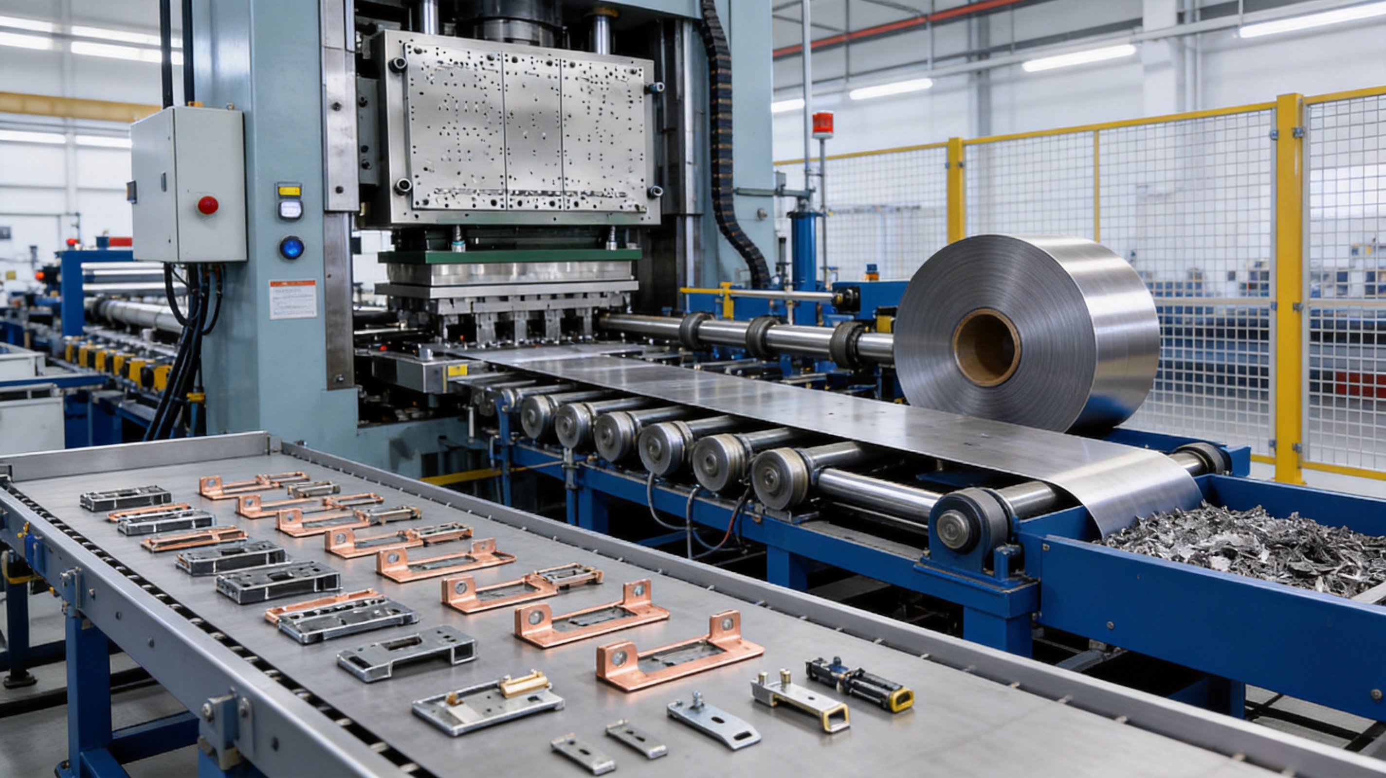
Questions and Answers
What types of parts are suitable for this progressive stamping die?
The tooling is suitable for many small and medium-sized metal components, including battery contact parts, busbar hardware, automotive electronic terminals, sensor components, small brackets, spring contacts, shielding parts, connector pins, switch components, and thin structural parts. Final suitability depends on part geometry, material, thickness, tolerance, volume, and press conditions.
Can the die perform both cutting and forming operations?
Yes. A customized multi-station tool can combine piercing, blanking, trimming, bending, forming, embossing, lancing, drawing, coining, and cutoff operations when the part design and material allow these processes to be integrated safely.
Is the tooling suitable for electric vehicle and new energy components?
Yes. The die is intended for applications such as battery contact components, busbar hardware, motor sheet metal parts, and other new energy hardware. These applications often require stable dimensions, repeatable electrical contact features, efficient production, and strong wear resistance.
How does modular insert construction reduce maintenance cost?
Modular construction allows selected wear or cutting components to be replaced individually. This can avoid replacing a larger die block, reduce repair time, simplify spare-parts management, and help return the tool to production more quickly.
What surface treatments are available?
Depending on the material and application, surface treatment options can include TD coating and PVD coating. The appropriate treatment is selected after considering wear, friction, production volume, material characteristics, forming conditions, and required service life.
How is dimensional accuracy verified before shipment?
The die undergoes trial production, and stamped samples are inspected against the customer’s approved drawings and requirements. Critical features may include hole position, profile, bend angle, formed height, flatness, burr, and surface condition. Inspection records and samples can be supplied for customer confirmation.
Can the supplier provide automation equipment as well as the die?
The company has stamping automation capabilities through its associated intelligent technology resources. Depending on the project, it can coordinate tooling with feeding, transfer, scrap removal, sensing, and other automation requirements to support a more complete production solution.
What press sizes can be supported?
The company has punch presses ranging from 80 tons to 400 tons. The appropriate press depends on the part, material, die size, calculated forming and cutting loads, stroke, shut height, and production speed. Final press compatibility should be confirmed during engineering review.
How long can the die operate before maintenance is required?
Maintenance intervals depend on material, thickness, cycle rate, lubrication, coating, die steel, part geometry, and operating conditions. Regular inspection is recommended rather than relying only on a fixed number of strokes. Wear indicators such as burr growth, dimensional drift, feeding problems, or unusual press load should be addressed promptly.
What information should be provided for a quotation?
The customer should provide part drawings or three-dimensional data, material grade and thickness, annual volume, required tolerances, press information, coil dimensions, surface requirements, inspection standards, and any downstream assembly or finishing requirements. Complete information enables a more accurate DFM review and quotation.
Conclusion
The high-precision multi-station progressive stamping die is a practical solution for manufacturers that require efficient, repeatable, and automated production of precision metal components. By integrating multiple operations into one die set, it can reduce manual handling, improve process continuity, support high output, and help control dimensional variation.
Its principal technical advantages include accurate guide systems, controlled strip feeding, modular inserts, optional TD and PVD surface treatments, customized station layouts, and complete pre-shipment validation. These features are reinforced by CNC machining, wire cutting, grinding, experienced assembly, die tryout, sample inspection, and automation coordination.
Suzhou Shuangqisi Mold Equipment Co., Ltd. combines die design and manufacturing with stamped hardware and automation capabilities. Its technical personnel, machining resources, press capacity, debugging experience, and integrated service model support customized tooling programs for automotive, electric vehicle, new energy, electronics, appliance, and telecommunications applications.
For manufacturers evaluating a long-term stamping solution, the most important consideration is not simply whether a die can produce a part. The tooling must also deliver stable quality, manageable maintenance, efficient material use, reliable automation, and predictable total cost. A carefully engineered multi-station progressive die can provide that foundation for mass production.
References
1. American Society of Mechanical Engineers. Fundamentals of Metal Forming and Press Tool Design.
2. Society of Manufacturing Engineers. Metal Stamping and Sheet Metal Forming Engineering Practices.
3. International Organization for Standardization. Quality Management Systems—Requirements.
4. International Organization for Standardization. Geometrical Product Specifications and Dimensional Verification Principles.
5. Schuler Group. Metal Forming Handbook.
6. ASM International. ASM Handbook: Volume 14B, Metalworking—Sheet Forming.
7. American National Standards Institute. Safety Requirements for the Construction, Care, and Use of Mechanical Power Presses.
Product: High Precision Stamping Die Multi Station Hardware Progressive Mold Tooling
Previous Post
No previous article
Next Post
Progressive Molds for Automotive Parts: Precision, Efficiency, and Reliable High-Volume Production
Our Products.
Start Your Business with an OEM Manufacturer Right Here!

Provide global customers with complete turn-key solutions
through
innovation!
QUICK LINKS
CONTACT INFO.
-
 +86-139 1308 8972
-

-
 No. 118 Yexin Road, Wujiang Economic Development Zone, Suzhou, China
Copyright © Suzhou Shuangqisi Mold Equipment Co., Ltd. All Rights Reserved. Custom Stamping Die Metal Stamping Die Manufacturers
