 English
 Español
 Deutsch

-
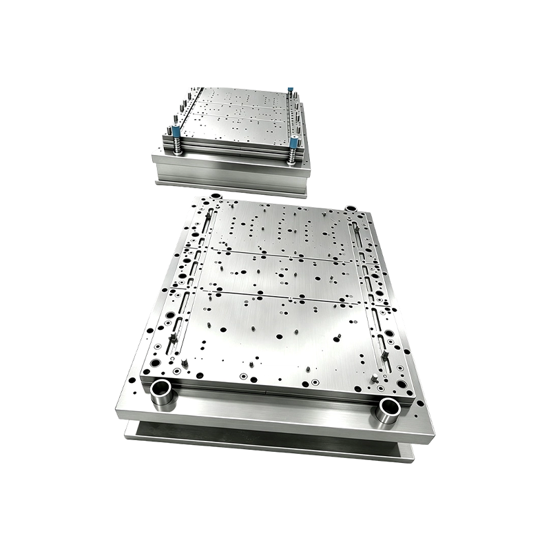
Progressive Stamping Die for Connector & Terminal Parts High Speed Progressive Stamping Die Precision Metal Hardware Stamping Tool mold for Connector Terminal Parts Automotive Components
Progressive Stamping Die for Connector & Termi...
-
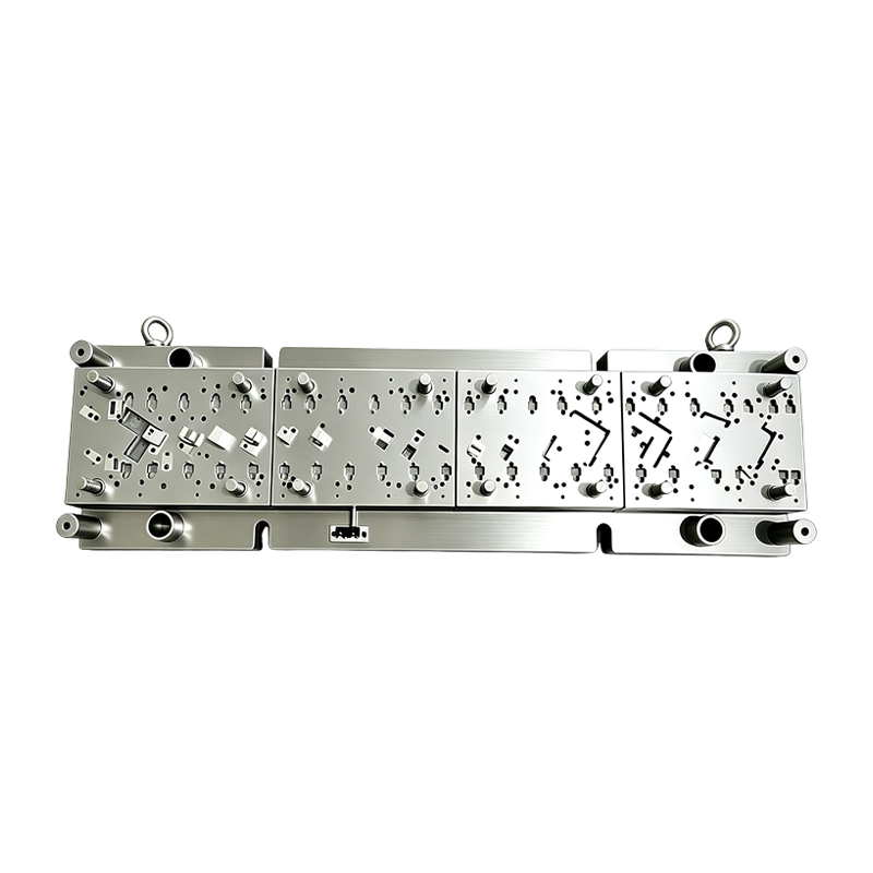
High Speed Progressive Stamping Die Sheet Metal Follow on Press Tool
Multi-operation Metal Stamping Tool for Continuous...
-
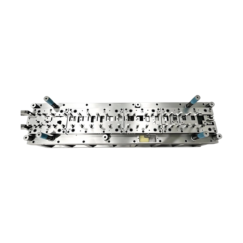
Long-Stroke Multi-Stage Progressive Die Automatic Strip Feed Progressive Die Long Travel Follow on Stamping Tool for Sheet Metal Hardware Press Moulding
Long-Stroke Multi-Stage Progressive DieOur custom ...
-
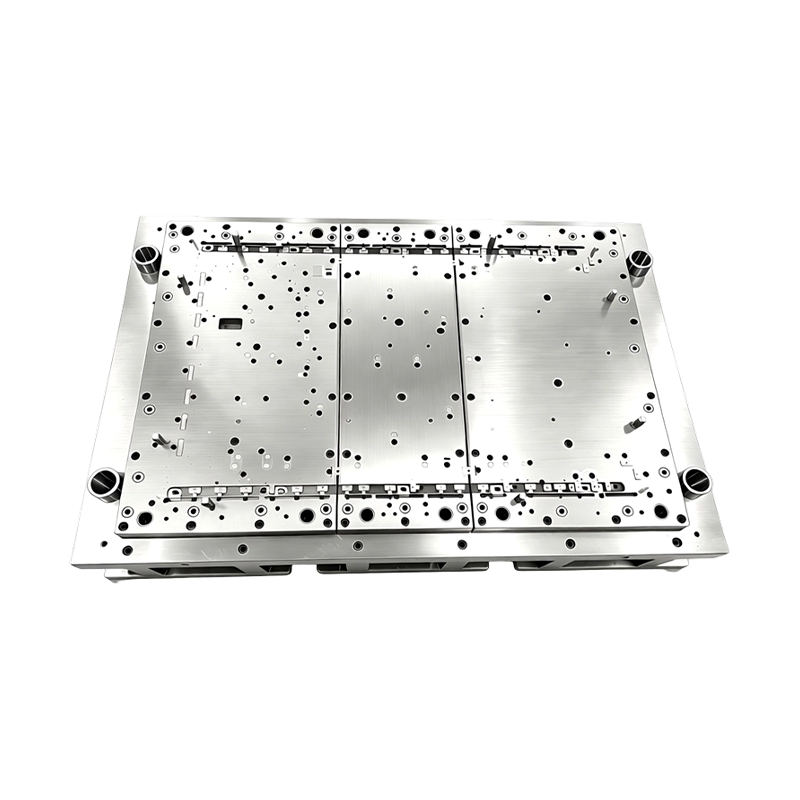
High Precision Stamping Die Multi Station Hardware Progressive Mold Tooling
Precision Metal Stamping Tool for Automotive &...
-
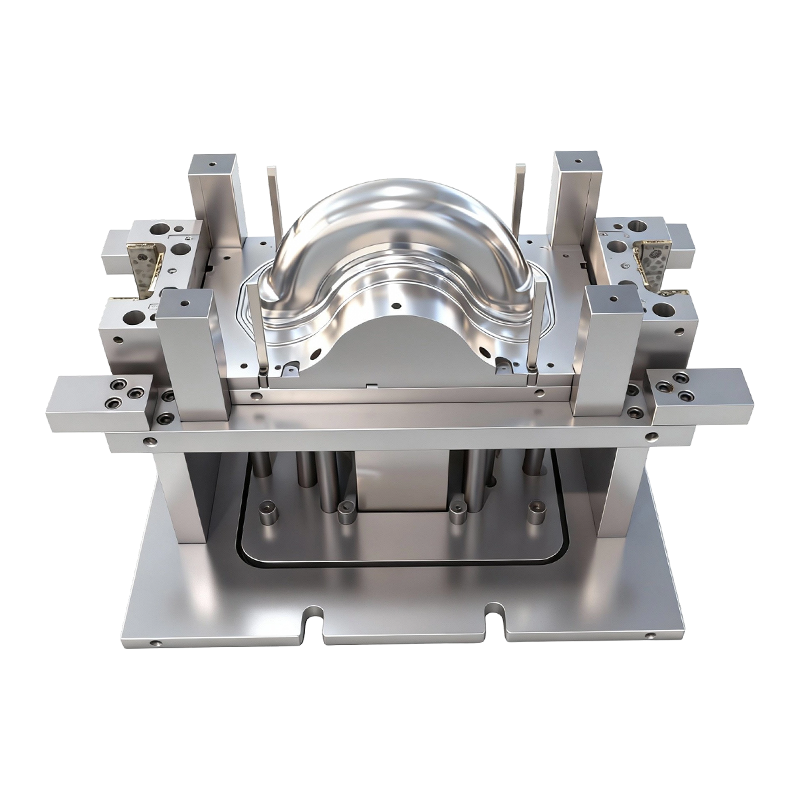
Deep drawing mold for front and rear wheels of two-wheeled electric vehicles
This Deep drawing mold for front and rear wheels o...
-
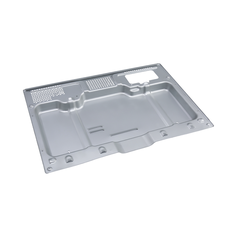
High-end oven stamping parts
Our High-end oven stamping parts are precision-man...
- E-mail us: [email protected]
- Call us: +86-139 1308 8972

Chen Siyi – Overseas Sales Manager
Home / Author / Chen Siyi – Overseas Sales Manager / High-Precision Compound Blanking and Piercing Dies for Flat Sheet Metal Components
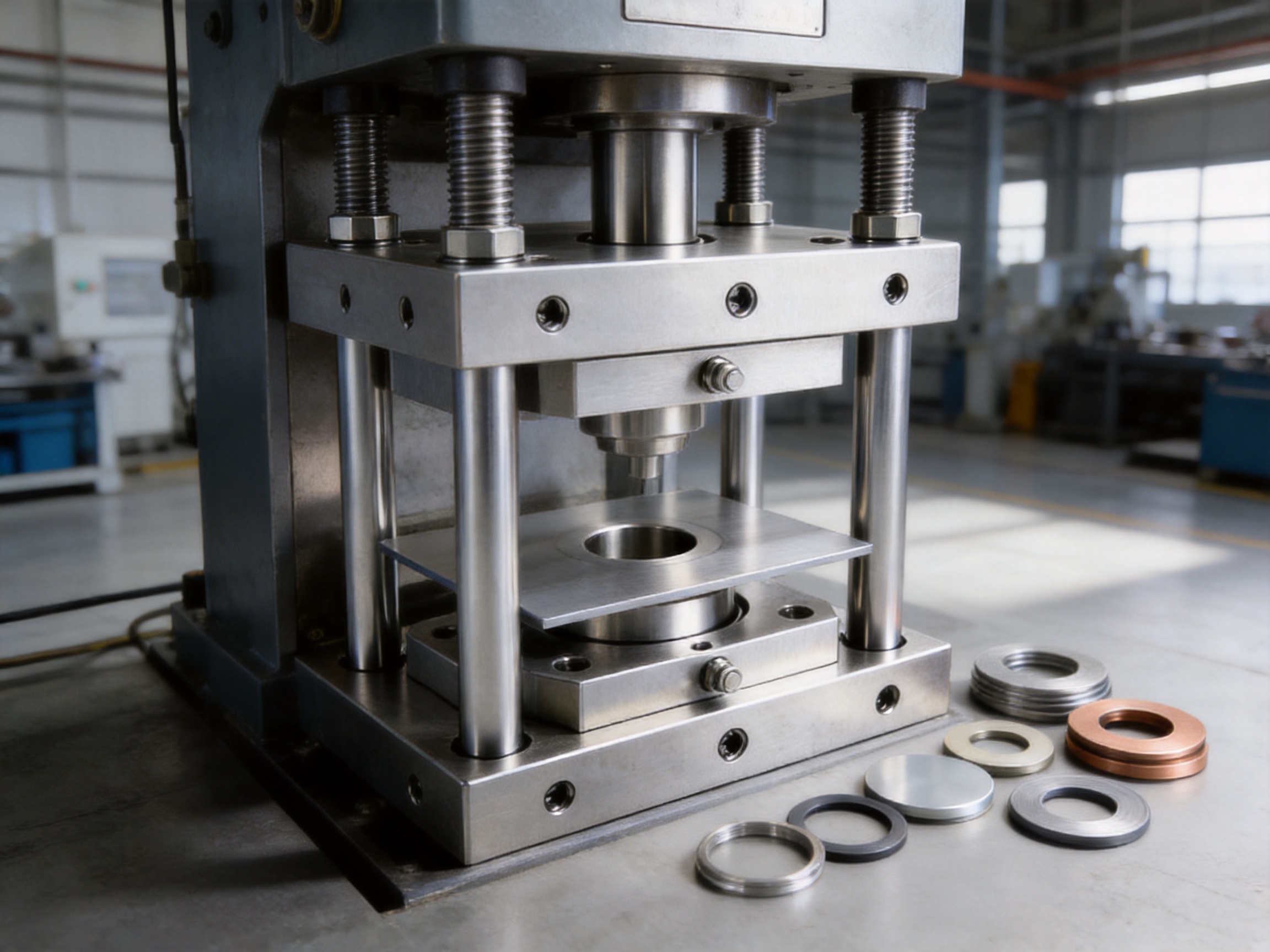
High-Precision Compound Blanking and Piercing Dies for Flat Sheet Metal Components
2026-09-20
Content
- 1 Introduction
- 2 What Is a Compound Blanking and Piercing Die?
- 3 Key Performance Advantages
- 4 Material and Thickness Capability
- 5 Engineering Design Considerations
- 6 Manufacturing Process and Quality Control
- 7 Manufacturing Resources and Company Strengths
- 8 Applications Across Industrial Sectors
- 9 Comparison with Other Die Concepts
- 10 Maintenance and Serviceability
- 11 Benefits for Production Economics
- 12 Information Required for a Custom Die Project
- 13 Why Choose an Integrated Die and Automation Supplier?
- 14 Quality, Delivery, and Technical Support
- 15 Frequently Asked Questions
- 15.1 What is the main purpose of a compound blanking and piercing die?
- 15.2 How does a compound die differ from a progressive die?
- 15.3 Can the die process stainless steel?
- 15.4 What material thickness can be handled?
- 15.5 What is the advantage of the four-pillar structure?
- 15.6 What is an integrated punch-die?
- 15.7 Can the die produce parts with high concentricity?
- 15.8 Is a compound die suitable for high-volume production?
- 15.9 Can the die be used for thin shim stock?
- 15.10 Can the supplier provide stamping automation?
- 15.11 What press capacity is required?
- 15.12 How often should the die be sharpened?
- 15.13 What industries can use this type of die?
- 16 Conclusion
- 17 References
- 18 Product: Compound Blanking & Piercing Die (4-Pillar, Single Station) High Precision Single Station Compound Stamping Tool 4-Pillar One Stage Blanking Piercing Die for Sheet Metal Parts
Introduction
Compound blanking and piercing dies are designed for sheet metal parts that require an outer profile and an internal opening to be produced in one press stroke. The compound blanking and piercing die described in this article combines a four-pillar heavy-duty die set, a single working station, and an integrated punch-die construction to deliver high dimensional consistency, excellent concentricity, and reliable production performance.
Unlike a progressive die, which transfers material through several stations, a compound die completes two or more cutting operations at one station. In this configuration, blanking and piercing occur simultaneously. The outer contour and the inner hole are therefore created under the same tooling alignment and during the same press cycle. This arrangement is especially advantageous for washers, shims, sealing rings, gaskets, bearing races, brake disc blanks, spacer rings, and other flat components in which the relationship between the internal and external geometries is critical.
The die is suitable for a broad range of sheet metals, including cold-rolled steel, stainless steel, copper, brass, aluminum, and other non-ferrous alloys. Depending on the material, part geometry, required cutting quality, and available press capacity, the tooling can be configured for material thicknesses ranging from thin shim stock of approximately 0.1 mm to structural plate of 6 mm or more.
Beyond the die itself, successful stamping depends on engineering discipline, machining accuracy, material control, press selection, inspection, sharpening, and maintenance. The manufacturing capabilities behind this type of tooling are therefore just as important as the design concept. A professional die manufacturer must be able to develop the working components, machine the die set, control cutting clearances, assemble the guide system, debug the tooling, and support production after delivery.
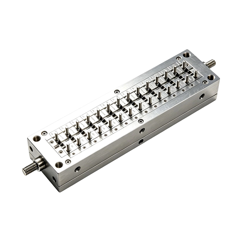
Compound Blanking & Piercing Die (4-Pillar, Single Station) High Precision Single Station Compound Stamping Tool 4-Pillar One Stage Blanking Piercing Die for Sheet Metal Parts
What Is a Compound Blanking and Piercing Die?
A compound die is a single-station stamping tool that performs multiple cutting operations during one stroke of a press. In a blanking and piercing application, one operation separates the outside shape of the part from the surrounding sheet while another creates a hole or internal opening in the same part. The two actions are coordinated within one die station.
The term “blanking” refers to cutting a finished piece from a sheet or strip. The cut-out piece is generally the required product, while the surrounding material becomes scrap. “Piercing” refers to creating a hole or internal opening, with the removed slug normally treated as scrap. When these operations are combined in a compound die, the finished blank and its internal feature are produced at the same time.
The core cutting components are arranged so that the material is supported and located precisely before the press applies force. The external profile and internal hole are then cut in a controlled sequence within the same stroke. Depending on the design, the part may be retained in the die while the surrounding scrap and piercing slug are removed separately. The exact ejection method is selected according to part size, material thickness, geometry, production volume, and press arrangement.
Single-Station Operation
The single-station design is one of the main advantages of this tooling concept. The material does not need to travel from a piercing station to a blanking station, and the part does not need to be repositioned between operations. This eliminates a major source of accumulated positioning error.
In a progressive die, each station must maintain a precise relationship with the previous station. Strip pitch, pilot engagement, carrier stability, material feeding, and station-to-station alignment all affect the final result. Progressive dies are highly productive for many parts, but the dimensional relationship between features can be influenced by the accuracy of multiple stations and by strip movement.
In a compound die, the inner and outer features are generated at the same location during the same press stroke. This can produce superior coaxiality and lower runout between the hole and the outside diameter, provided that the die has been properly designed, manufactured, assembled, and adjusted.
Integrated Punch-Die Construction
The working element is based on an integrated punch-die, sometimes described as a convex-concave die or combination punch-die. It performs complementary cutting functions within the same tool arrangement. By integrating the relevant working surfaces, the design reduces the number of independent components that must remain aligned during operation.
This construction can reduce alignment errors, simplify the working area, and make the die easier to set up. It may also help reduce overall die height when compared with arrangements that use multiple independent stations. For maintenance personnel, fewer moving and positioning elements can mean easier access to cutting edges and a more straightforward sharpening process.
Key Performance Advantages
High Concentricity Between Inner and Outer Features
For a washer, bearing race, spacer, sealing ring, or circular plate, the location of the inner hole relative to the outer diameter is often more important than either dimension alone. Excessive eccentricity can create uneven loading, poor sealing, vibration, imbalance, or difficulty during assembly.
Because blanking and piercing are executed at one station, the compound die provides a direct method for controlling this relationship. The same guide system, die alignment, and material location are used for both cutting operations. There is no need to transfer a partially processed part from one station to another, so the risk of inter-station positional variation is reduced.
The resulting coaxiality depends on several factors, including guide pillar accuracy, punch and die concentricity, cutting clearance, material flatness, press parallelism, die deflection, and the quality of the incoming sheet. Nevertheless, the single-station concept offers an inherent advantage for parts with strict inner-to-outer alignment requirements.
Excellent Flatness
Flatness is essential for gaskets, shims, motor plates, sealing washers, electrical shielding plates, and structural rings. A part that leaves the press with excessive bow, twist, or local distortion may require a secondary flattening operation, increasing production cost and reducing throughput.
Compound blanking and piercing can support good flatness because the part is controlled in one cutting event rather than being carried between several stations. There is no progressive strip carrier bending the part during transfer, and there is less opportunity for intermediate handling to introduce deformation.
Flatness is also influenced by material condition, residual stress in the sheet, clearance selection, cutting edge condition, press rigidity, and the design of the stripper or pressure pad. A properly engineered die can minimize deformation, but the tooling should always be evaluated together with the selected material and the production press.
Reduced Positioning Distortion
Every additional handling or transfer step introduces a potential source of variation. In a multi-station process, the strip must advance accurately, pilots must enter correctly, carriers must remain stable, and each station must maintain its intended relationship. A compound tool avoids many of these requirements for parts that can be completed in one station.
This does not mean that a compound die is automatically the best choice for every product. Progressive tooling may be more appropriate for parts with several forming stages, multiple holes, tabs, louvers, or complex three-dimensional features. However, for relatively flat parts with a small number of cutting operations, the compound approach can provide a strong balance of precision, simplicity, and repeatability.
Rigid Four-Pillar Die Set
The four-pillar die set provides a stable structural foundation for high-force cutting. Four guide pillars and matched guide bushings help maintain parallel movement between the upper and lower sections of the die. Compared with less rigid arrangements, the four-pillar design offers stronger resistance to lateral movement and tilting.
During blanking and piercing, cutting forces are not always perfectly balanced. Asymmetrical part shapes, uneven scrap distribution, material variation, or multiple cutting edges can create lateral loads. A rigid guide system helps prevent these loads from shifting the working components out of alignment.
Parallelism is particularly important when producing thick or high-strength materials. If the upper and lower components do not remain parallel, the cutting clearance can vary across the profile. This may cause excessive burrs in one area, premature edge wear, poor part quality, or localized die damage. A properly fitted four-pillar system helps maintain consistent clearance throughout the working area.
Stable Performance During Long Production Runs
Production tooling must do more than create an accurate first part. It must maintain acceptable quality through repeated cycles. Stability depends on the die structure, guide system, cutting material, heat treatment, press condition, lubrication, scrap removal, and maintenance schedule.
The heavy-duty four-pillar construction supports long production runs by reducing lateral movement and maintaining the relationship between the upper and lower die sections. The design is also compatible with presses in a range of capacities, with the final press selection determined by material thickness, shear perimeter, part geometry, stripping force, and safety margin.
Material and Thickness Capability
The compound die can be engineered for many common industrial sheet materials. Each material requires an appropriate combination of cutting clearance, tool steel, edge preparation, press force, lubrication, and surface treatment. A cutting condition suitable for soft aluminum may not be suitable for stainless steel or high-strength steel.
| Material | Typical Considerations | Potential Applications |
|---|---|---|
| Cold-rolled steel | Stable sheet condition and broad availability; clearance depends on grade and thickness. | Washers, brackets, shims, structural blanks, motor plates. |
| Stainless steel | Higher strength and work-hardening tendency; requires suitable clearance and edge durability. | Sealing rings, medical blanks, hardware, appliance components. |
| Copper | Soft and conductive; may require attention to burr control and surface protection. | Electrical contacts, busbar blanks, terminal parts. |
| Brass | Good formability and machinability; cutting behavior varies by alloy. | Electrical hardware, washers, spacers, connector parts. |
| Aluminum | Lightweight material that may adhere to tooling if the cutting condition is not optimized. | Lightweight plates, sealing washers, structural rings. |
| Non-ferrous alloys | Tooling parameters should be selected according to alloy hardness and surface condition. | Specialized electrical, industrial, and mechanical components. |
Thin materials from approximately 0.1 mm can be processed when the die is designed for fine control of clearance, support, and stripping. Very thin sheet requires careful handling because it can buckle, curl, or become trapped in the cutting area if the pressure and ejection systems are not properly configured.
Materials around 6 mm thick or more may also be processed when the press has sufficient tonnage and the die structure is designed for the required load. Thick plate generates substantial cutting force and may require specialized edge geometry, stronger tool materials, increased die clearance, and robust scrap management. The actual capability should be confirmed through engineering review rather than determined solely by nominal thickness.
Engineering Design Considerations
Cutting Clearance
Cutting clearance is the gap between the cooperating cutting edges. It is one of the most important parameters in a blanking and piercing die. If the clearance is too small, cutting force and wear may increase, and the material may fracture improperly. If the clearance is too large, burrs, rollover, dimensional variation, and poor edge quality may result.
The correct clearance depends on material type, thickness, hardness, tensile strength, required edge quality, and production objectives. A precision part may require a more carefully controlled clearance than a general-purpose structural blank. In some applications, the die may be designed to balance tool life and edge quality rather than maximize one characteristic alone.
Press Tonnage
The press must provide sufficient force for blanking, piercing, stripping, and any additional operations. Tonnage is influenced by the total cutting perimeter, material thickness, material shear strength, and the timing of the cutting actions. The die should not be matched to a press based only on the nominal size of the finished part.
Insufficient press capacity can lead to incomplete cutting, excessive deflection, unstable operation, and premature failure. Excessively large presses may also be unsuitable if the available stroke, shut height, or energy characteristics do not match the die. A professional tooling supplier should review the press specifications before finalizing the design.
Stripper and Pressure Control
The stripper removes material from the punch and helps control the sheet during cutting. Its function is important for part flatness, operator safety, scrap separation, and repeatable operation. In some applications, a pressure pad or other controlled holding system is used to support the sheet and prevent lifting or distortion.
For thin stock, the stripper must be carefully balanced. Excessive pressure may mark or deform the sheet, while insufficient pressure may allow movement and produce dimensional variation. For thick or high-strength materials, the stripper must withstand larger forces and maintain stable contact through the cutting cycle.
Slug and Scrap Management
Compound dies generate both the finished blank and piercing scrap. Reliable removal is necessary to avoid slug stacking, die blockage, tool damage, and production interruption. Scrap paths should be designed according to the part geometry, press direction, available space, and automation method.
Where appropriate, the die may use gravity discharge, air blow-off, mechanical ejection, or a dedicated scrap chute. The choice depends on the size and shape of the slug, the material, the cycle rate, and the customer’s production environment. Scrap management should be tested during die tryout and confirmed under realistic production conditions.
Manufacturing Process and Quality Control
High-precision stamping performance begins with a controlled manufacturing process. The die manufacturer described in the supplied company information integrates design, machining, assembly, debugging, and service. This integrated structure enables the engineering team to manage the relationship between the working components and the final stamping result.
Product and Process Review
The process normally begins with a review of the customer’s drawings, three-dimensional data, material specifications, thickness range, production volume, press information, tolerance requirements, and inspection standards. The design team evaluates whether a compound die is appropriate or whether a progressive, transfer, or other tooling concept would provide better overall value.
For a compound blanking and piercing application, the review should focus on outer profile accuracy, hole location, concentricity, flatness, edge quality, burr direction, material utilization, and ejection requirements. The team should also consider whether the part contains features that cannot be produced by cutting alone.
Die Design
Once the process concept is approved, the die is designed around the part geometry and press conditions. Important elements include the four-pillar die set, guide pillar arrangement, integrated punch-die, stripper or pressure pad, cutting clearance, material support, scrap discharge, fasteners, wear components, and access for maintenance.
Die design should include sufficient space for inspection and sharpening. Cutting edges are wear items, and practical access can reduce maintenance time. The design should also consider the expected service life, replacement strategy, spare parts, and the customer’s ability to perform routine maintenance.
Precision Machining
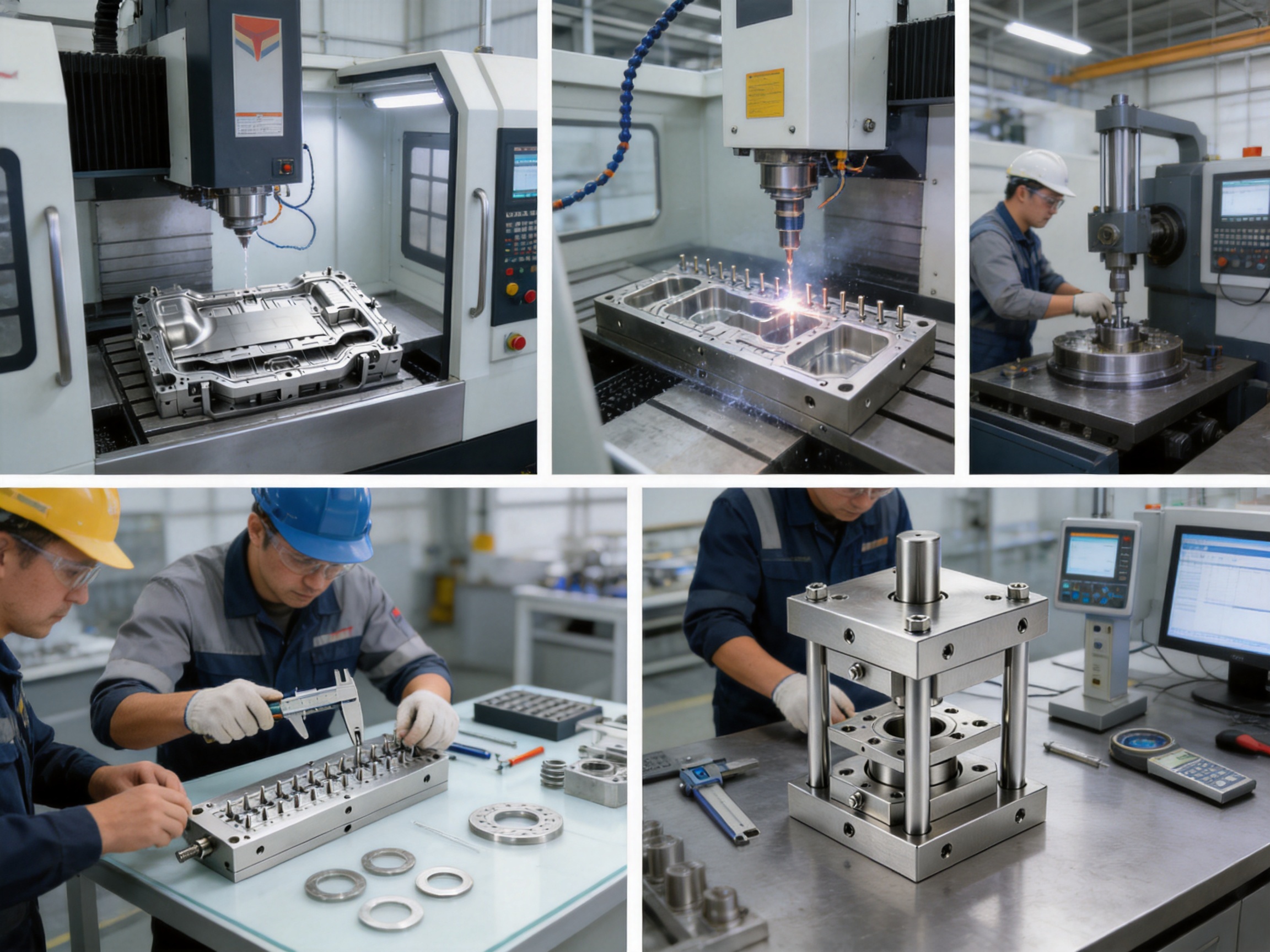
Precision machining is required to create the working profiles and accurately locate the guide and mounting features. The manufacturing facility is equipped with imported wire cutting machines, CNC machining centers, and more than ten grinding machines of different sizes. These resources support the production of close-tolerance components and allow different machining methods to be selected according to geometry and material.
Wire electrical discharge machining is particularly useful for detailed cutting profiles, narrow slots, complex internal contours, and hardened tool components. CNC machining centers can produce die plates, mounting surfaces, pockets, holes, and structural features with repeatable positioning. Grinding is used to improve surface quality, dimensional accuracy, parallelism, and the condition of critical working faces.
Using multiple machining capabilities within one organization can shorten coordination time and improve process control. It also allows experienced technicians to choose a practical sequence for rough machining, semi-finishing, heat treatment, wire cutting, grinding, fitting, and final inspection.
Heat Treatment and Tool Life
Cutting components must withstand repeated impact, compression, friction, and edge pressure. Tool steels and other wear-resistant materials are selected according to the material being stamped, production volume, required edge life, and maintenance plan. Heat treatment may be used to provide the necessary hardness and toughness, with the final condition verified according to the tooling specification.
High hardness alone is not sufficient. A cutting component that is too brittle may chip, while one that is too soft may wear rapidly or lose its geometry. The material and heat-treatment condition should therefore be chosen as part of a balanced tool-life strategy.
Grinding and Fitting
Grinding contributes to the flatness and parallelism of die plates, the accuracy of cutting edges, and the fit between cooperating components. Skilled fitting is also essential. Even accurately machined components must be assembled with attention to alignment, contact, clearance, movement, and support.
During fitting, technicians verify that the guide pillars move smoothly, the working components meet correctly, the stripper operates without interference, and the die can be safely opened and maintained. The integrated punch-die must be positioned so that the inner and outer cutting profiles remain concentric throughout the press stroke.
Die Tryout and Debugging
Before delivery, the die is tested in a controlled tryout process. The objective is not only to produce a part but also to evaluate the complete operating behavior of the tooling. Technicians inspect the first stamped samples for dimensions, hole location, concentricity, burrs, flatness, edge rollover, surface marks, and scrap discharge.
If necessary, adjustments may be made to cutting clearance, stripper pressure, guide components, feed position, ejection timing, or other elements. The die is then tested again until it meets the agreed technical requirements. Experienced debugging personnel are especially important for compound tooling because small alignment or clearance variations can affect both the inner and outer features simultaneously.
Manufacturing Resources and Company Strengths
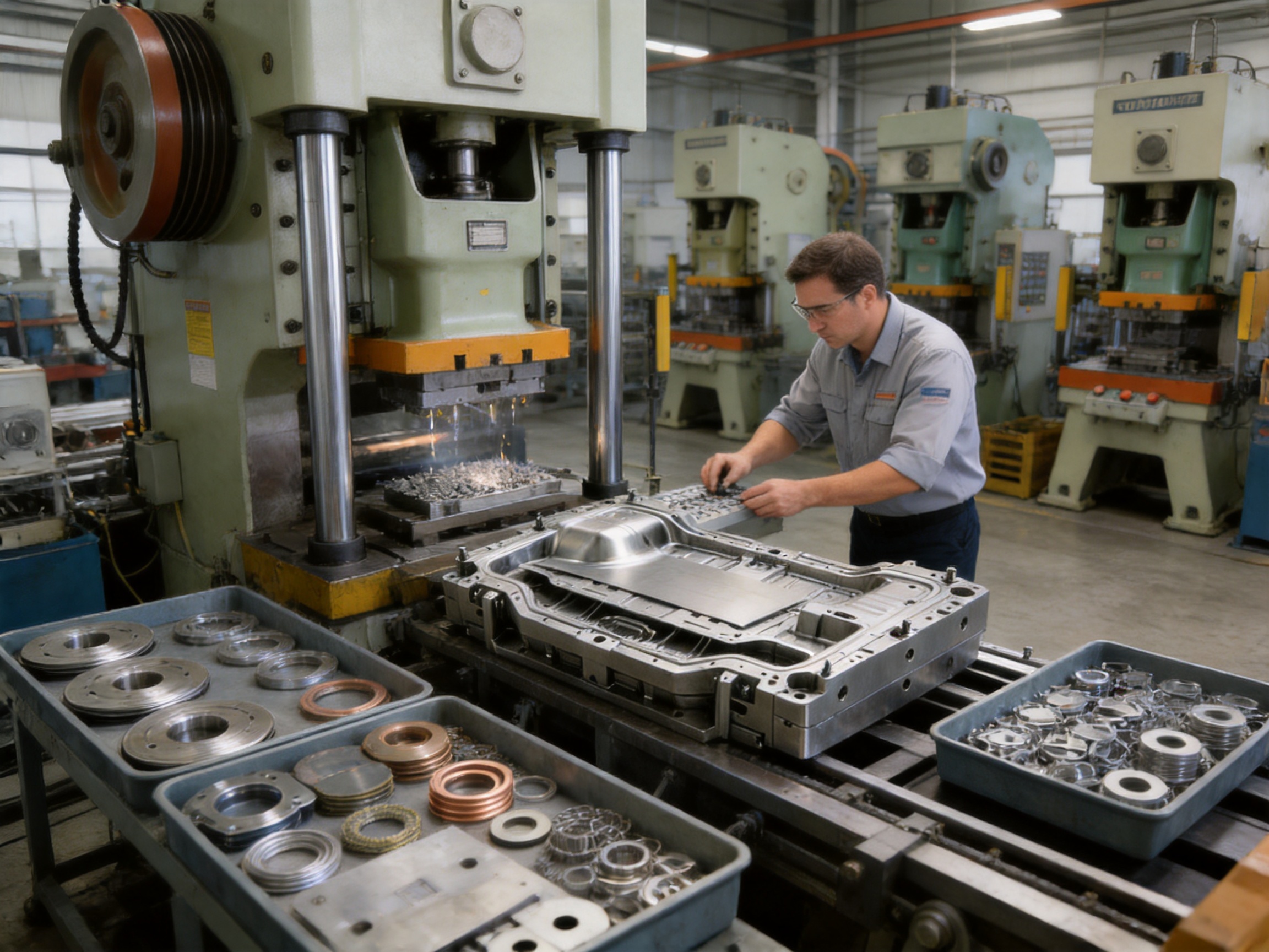
The manufacturer behind this product has approximately 15 years of experience in the mold industry and a technical workforce of around 60 employees. Its equipment includes imported wire cutting machines, CNC machining centers, more than 10 grinding machines, and 25 punch presses with capacities ranging from 80 tons to 400 tons.
This combination of equipment and personnel provides several practical advantages. First, the company can develop and manufacture stamping dies using in-house resources rather than relying entirely on external processing. Second, the available press range enables die tryout across different capacity levels. Third, experienced operators and debugging personnel can identify production issues before the tooling reaches the customer’s factory.
The company also manufactures stamping hardware parts and provides stamping automation equipment through an associated intelligent technology operation established in 2016. This creates the potential for a broader turnkey solution that includes dies, automation equipment, production support, and related manufacturing equipment.
Integrated capabilities are valuable when a customer is planning a complete production line rather than purchasing a standalone die. Automation may include feeding, material handling, part collection, scrap removal, transfer arrangements, and production monitoring. The most suitable configuration depends on the part, material, press, cycle time, and factory layout.
The company’s customer base includes organizations in servo drives, compressors, and new energy vehicles, as well as other industrial sectors. Its reported strengths include technical experience, cost control, quality management, and the ability to combine die manufacturing with stamping automation. These capabilities are relevant to customers seeking a supplier that can support both tooling development and production implementation.
Applications Across Industrial Sectors
Automotive Components
Automotive applications often require repeatable dimensions, stable flatness, and reliable high-volume production. Compound blanking and piercing dies can be used for brake disc blanks, clutch plates, thrust washers, bearing races, gear blanks, exhaust gaskets, and shim packs. The single-station arrangement is particularly useful when the outer contour and inner opening must remain accurately aligned.
For automotive parts, the die design should be reviewed against material grade, burr limitations, cleanliness requirements, press cycle, and downstream assembly conditions. Where the blank will undergo additional forming, the blanking edge and dimensional consistency may affect later operations.
Industrial Fasteners and Hardware
Flat washers, sealing rings, spacers, flange gaskets, and related hardware are common compound-die products. These parts often have relatively simple two-dimensional geometry but are produced in large quantities. Tool life, quick sharpening, material utilization, and low downtime are therefore important.
A single-station compound die can be advantageous when the part does not require multiple forming steps. The die can produce the finished outline and central hole together, reducing handling and helping maintain the relationship between the two features.
Electrical and Electronic Components
Electrical applications include contact pads, terminal blanks, EMI shielding plates, copper or brass washers, and selected motor lamination prototypes. Material conductivity, burr direction, edge quality, and surface condition may be important to electrical performance or assembly.
For thin conductive materials, the die must be designed to prevent distortion and excessive burrs. The material should be properly supported, and the cutting edges should be maintained to avoid damaging delicate surfaces.
Aerospace Components
Aerospace production can use compound dies for precision shims, spacer rings, turbine disc blanks, and selected structural plate components. These applications may involve strict documentation, material traceability, dimensional inspection, and process approval requirements.
The die itself should be manufactured and validated according to the customer’s quality system and technical documentation requirements. The tooling concept must also be evaluated in relation to the material grade and the required post-processing operations.
Medical Devices
Medical device production may involve surgical instrument blanks, implant spacer rings, and precision medical shims. These applications commonly require careful control of material identity, cleanliness, burrs, dimensional accuracy, and inspection records.
A compound die can be suitable when a flat part requires a highly controlled inner-to-outer relationship. However, the tooling and production process must be integrated into the customer’s applicable quality system. For organizations operating under ISO 13485 or similar requirements, supplier qualification and process validation should be completed according to the customer’s procedures.
Home Appliances
Motor end plates, compressor valve plates, sealing washers, bracket blanks, and other appliance components can benefit from repeatable blanking and piercing. High production volumes make cycle stability, die life, maintenance access, and material utilization important considerations.
New Energy Equipment
New energy applications include battery busbar blanks, cooling plate preforms, motor stator segment blanks, and structural spacers. Copper and aluminum are frequently used in electrical and thermal systems, while steel and stainless steel may be used for structural or protective parts.
These applications may involve increasingly demanding requirements for burr control, flatness, dimensional repeatability, and clean handling. The compound die can provide a practical solution for flat components where the inner and outer profiles must be produced in a controlled relationship.
Comparison with Other Die Concepts
| Criterion | Compound Die | Progressive Die | Transfer Die |
|---|---|---|---|
| Number of primary stations | One station for simultaneous operations. | Several stations arranged along a strip. | Several stations with part transfer between operations. |
| Inner-to-outer alignment | Strong potential for high concentricity because features are cut together. | Depends on strip pitch, pilot accuracy, and station alignment. | Depends on transfer accuracy and part location at each station. |
| Best suited for | Flat parts with multiple cutting features. | High-volume parts with multiple cutting or forming stages. | Larger or three-dimensional parts requiring sequential operations. |
| Tooling complexity | Generally lower than multi-station tooling for simple flat parts. | Higher due to several stations and strip management. | Higher due to transfer mechanisms and multiple operations. |
| Setup and maintenance | Relatively simple; cutting edges can be accessed for sharpening. | More complex; multiple stations require coordinated maintenance. | More complex; transfer systems require additional adjustment. |
| Production flexibility | Strong for a defined flat part and material range. | Strong for repeat high-volume production of complex strip layouts. | Strong for multi-operation formed components. |
The comparison shows why die selection should be based on the part and process rather than on production volume alone. A progressive die may be more economical for a complex part containing many operations, even if the initial tooling investment is higher. A compound die may be more effective for a flat ring or plate in which concentricity and flatness are the main objectives.
Compound tooling can also be attractive for medium-volume production, prototype programs, replacement parts, and applications where a customer wants a robust but comparatively straightforward tool. The final decision should include cycle time, material utilization, labor, maintenance, press availability, inspection requirements, and the cost of secondary operations.
Maintenance and Serviceability
One advantage of the single-station configuration is its relatively straightforward maintenance structure. With fewer stations and fewer transfer components, technicians can inspect the working area, clean the die, monitor wear, and perform sharpening without managing a long sequence of independent operations.
Cutting edges should be inspected at regular intervals for rounding, chipping, galling, burr growth, and dimensional drift. A gradual increase in burr height is often an early indication that the cutting edges require attention. Continuing to run a worn die can increase press load and damage other components.
Sharpening should remove only the necessary amount of material while preserving the original geometry. After sharpening, the die may require adjustment of stripper height, spacer dimensions, or other related components. The maintenance procedure should be documented so that repeated sharpening does not gradually alter the intended shut height or cutting condition.
Guide pillars and bushings should be kept clean and lubricated according to the supplier’s recommendations. Contamination or insufficient lubrication can increase friction and reduce alignment accuracy. Bolts, wear plates, springs, and ejection components should also be inspected during scheduled maintenance.
Scrap passages must remain clear. A blocked slug path can cause the next stroke to force material into an occupied space, potentially damaging the punch-die or die plate. Operators should follow safe shutdown and cleaning procedures, and maintenance should be performed only by qualified personnel.
Benefits for Production Economics
The economic value of a compound die comes from more than its purchase price. It should be evaluated through the complete production process. A die that reduces secondary flattening, minimizes part repositioning, improves concentricity, and simplifies maintenance may deliver lower total cost over its service life.
Single-station processing can reduce the number of process steps for suitable parts. Fewer steps may mean less handling, fewer intermediate inspections, lower work-in-process inventory, and fewer opportunities for damage. If the finished component leaves the die with the required flatness and alignment, secondary correction may be reduced or eliminated.
Maintenance efficiency can also affect operating cost. A design that provides convenient access to cutting edges allows maintenance personnel to respond quickly to wear. Shorter sharpening and setup periods can increase available press time and improve delivery performance.
Material utilization remains an important consideration. Although a compound die uses one station, the blank layout and scrap pattern still influence material cost. The die designer should review the blanking arrangement, edge margin, sheet size, nesting opportunities, and scrap removal method before finalizing the tooling.
Information Required for a Custom Die Project
Customers requesting a compound blanking and piercing die should provide as much technical information as possible. Accurate input allows the supplier to select the proper construction, calculate press requirements, and identify potential production risks before manufacturing begins.
Part drawings or three-dimensional models.
Outer profile dimensions and internal feature dimensions.
Required concentricity, runout, flatness, burr, and dimensional tolerances.
Material grade, hardness, surface condition, and thickness range.
Expected annual volume and target production speed.
Available press tonnage, stroke, shut height, bolster dimensions, and slide specifications.
Preferred feeding method and sheet or coil format.
Part collection and scrap removal requirements.
Inspection standards and documentation requirements.
Packaging, spare parts, maintenance, and training expectations.
When the application involves stainless steel, high-strength steel, copper, aluminum, medical materials, or special surface requirements, those conditions should be identified at the beginning of the project. Early communication reduces the risk of selecting a tool material or cutting clearance that is unsuitable for the intended production environment.
Why Choose an Integrated Die and Automation Supplier?
A die is only one part of a stamping process. The feeding method, press, automation, scrap collection, inspection, and operator procedures all influence output quality. An integrated supplier can evaluate these elements together and provide a more coordinated solution.
The manufacturer associated with this product combines stamping die design and manufacturing with stamping automation capabilities. Through its related intelligent technology operation, it can support customers seeking automation equipment in addition to tooling. Depending on the project, this may help reduce the number of interfaces between different suppliers.
A coordinated supplier can also consider future production requirements. A customer may initially require a standalone die for manual loading, then later plan to introduce automatic feeding or part collection. If the tooling and automation are developed with compatible interfaces, the transition can be easier.
Integrated manufacturing also supports practical feedback. Press operators, die makers, machinists, and debugging technicians can communicate directly about issues such as material feeding, slug discharge, burr growth, or die access. This feedback can be used to improve the design before final delivery.
Quality, Delivery, and Technical Support
Reliable tooling supply requires more than machining components to a drawing. The supplier should manage design review, process planning, component inspection, assembly, tryout, sample evaluation, correction, and final acceptance. Clear communication at each stage helps ensure that the finished die meets the customer’s production objectives.
The company’s stated experience, equipment base, technical personnel, and press resources support this type of project management. Its customer industries include servo drives, compressors, and new energy vehicles, where stamping quality and delivery reliability are important. The ability to provide competitive pricing while maintaining process control can be useful for both established manufacturers and customers developing new production programs.
Technical support should continue after the die is delivered. Useful support may include installation guidance, press setup recommendations, sharpening instructions, spare component supply, troubleshooting, and advice on process optimization. For customers purchasing automation equipment, support may also include commissioning and integration assistance.
Frequently Asked Questions
What is the main purpose of a compound blanking and piercing die?
The main purpose is to produce a part’s outer profile and internal hole in one press stroke at one station. This is particularly useful for flat components requiring close control of concentricity, flatness, and dimensional repeatability.
How does a compound die differ from a progressive die?
A compound die completes multiple cutting operations at one station, while a progressive die moves strip material through several stations. A compound die can provide strong inner-to-outer alignment for suitable flat parts, whereas a progressive die is often better for parts requiring many sequential cutting and forming operations.
Can the die process stainless steel?
Yes. Stainless steel can be processed when the die is designed for the specific grade, thickness, hardness, and production volume. Proper cutting clearance, durable tool materials, adequate press capacity, and suitable maintenance are important for stainless steel applications.
What material thickness can be handled?
The stated range is approximately 0.1 mm to 6 mm or thicker, depending on the material, part geometry, press tonnage, die construction, and required edge quality. The actual thickness range should be confirmed during engineering review.
What is the advantage of the four-pillar structure?
The four-pillar structure improves guidance, parallelism, and lateral rigidity between the upper and lower die sections. This helps maintain consistent cutting clearance and reduces the risk of die shift during high-force or long-run production.
What is an integrated punch-die?
An integrated punch-die is a precision working component that combines cooperating cutting functions within the compound tooling arrangement. It helps reduce alignment errors between separate components and can simplify die setup and maintenance.
Can the die produce parts with high concentricity?
It is designed for high concentricity because the blanking and piercing operations occur simultaneously at the same station. Final concentricity depends on the tooling accuracy, material condition, press alignment, cutting clearance, and production setup.
Is a compound die suitable for high-volume production?
It can be suitable for high-volume production when the part is appropriate for single-station processing and the die is designed with sufficient wear resistance, reliable scrap removal, and convenient maintenance access. Production volume alone should not determine die selection.
Can the die be used for thin shim stock?
Yes. Thin materials can be processed when the die provides accurate support, suitable pressure control, and carefully selected cutting clearance. Thin stock requires special attention to handling, flatness, and part ejection.
Can the supplier provide stamping automation?
The company has related capabilities in stamping automation equipment and can provide turnkey solutions involving stamping dies and automation. The precise automation configuration depends on the press, material format, cycle rate, feeding method, and part-handling requirements.
What press capacity is required?
The required capacity depends on the total cutting perimeter, material strength, material thickness, stripping force, and safety margin. The manufacturer operates punch presses from approximately 80 tons to 400 tons and can evaluate the requirements based on the customer’s part and press information.
How often should the die be sharpened?
Sharpening frequency depends on material, production volume, clearance, tool steel, lubrication, and the acceptable burr limit. Operators should monitor burr height, dimensional change, cutting noise, and press load rather than rely only on a fixed cycle count.
What industries can use this type of die?
Applications include automotive, industrial hardware, electrical and electronics, aerospace, medical devices, home appliances, compressors, servo drives, and new energy equipment. The common requirement is a relatively flat component with accurately related internal and external features.
Conclusion
The four-pillar, single-station compound blanking and piercing die is a high-precision solution for flat sheet metal components that require simultaneous outer-profile and internal-hole cutting. Its principal advantages are strong potential for concentricity, good flatness, reduced repositioning distortion, rigid guidance, and relatively straightforward maintenance.
The integrated punch-die construction helps simplify the working arrangement, while the four-pillar die set supports parallel movement and stable cutting clearance. The design can be adapted to materials ranging from thin shim stock to thicker structural plate, subject to press capacity and application-specific engineering.
Compared with progressive and transfer tooling, the compound die is especially competitive when the part is flat, the number of cutting operations is limited, and the relationship between the inner and outer features is critical. It may reduce secondary operations, simplify setup, and provide consistent production quality over extended runs.
The manufacturer’s capabilities strengthen the product offering. With experienced technical staff, imported wire cutting equipment, CNC machining centers, multiple grinding machines, punch presses from 80 to 400 tons, and related stamping automation resources, the company can support projects from die design through machining, assembly, debugging, and production integration.
For customers in automotive, electrical, compressor, appliance, medical, aerospace, and new energy industries, this tooling concept provides a practical foundation for producing accurate, flat, and repeatable metal components. The best results are achieved when the die is engineered together with the material, press, feeding method, inspection requirements, and maintenance plan.
References
1. Design principles for compound stamping dies, including blanking, piercing, cutting clearance, stripping, and die alignment.
2. Industrial pressworking guidelines for calculating blanking force, piercing force, stripping force, and press capacity.
3. Manufacturing references covering wire electrical discharge machining, CNC die machining, precision grinding, heat treatment, and tool-steel selection.
4. Quality management principles for stamping die design, tryout, inspection, maintenance, and production validation.
5. ISO 13485 quality management considerations for suppliers serving medical device manufacturing applications.
6. General engineering practices for progressive, compound, transfer, and single-operation sheet metal stamping processes.
Product: Compound Blanking & Piercing Die (4-Pillar, Single Station) High Precision Single Station Compound Stamping Tool 4-Pillar One Stage Blanking Piercing Die for Sheet Metal Parts
Previous Post
Long-Stroke Multi-Stage Progressive Dies for Complex Sheet Metal Forming
Next Post
Heavy Truck Stamping Parts: Precision Components for Reliable Commercial Vehicles
Our Products.
Start Your Business with an OEM Manufacturer Right Here!

Provide global customers with complete turn-key solutions
through
innovation!
QUICK LINKS
CONTACT INFO.
-
 +86-139 1308 8972
-

-
 No. 118 Yexin Road, Wujiang Economic Development Zone, Suzhou, China
Copyright © Suzhou Shuangqisi Mold Equipment Co., Ltd. All Rights Reserved. Custom Stamping Die Metal Stamping Die Manufacturers
