 English
 Español
 Deutsch

-
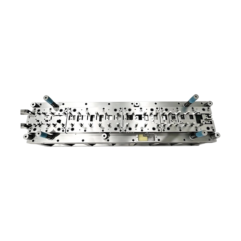
Long-Stroke Multi-Stage Progressive Die Automatic Strip Feed Progressive Die Long Travel Follow on Stamping Tool for Sheet Metal Hardware Press Moulding
Long-Stroke Multi-Stage Progressive DieOur custom ...
-
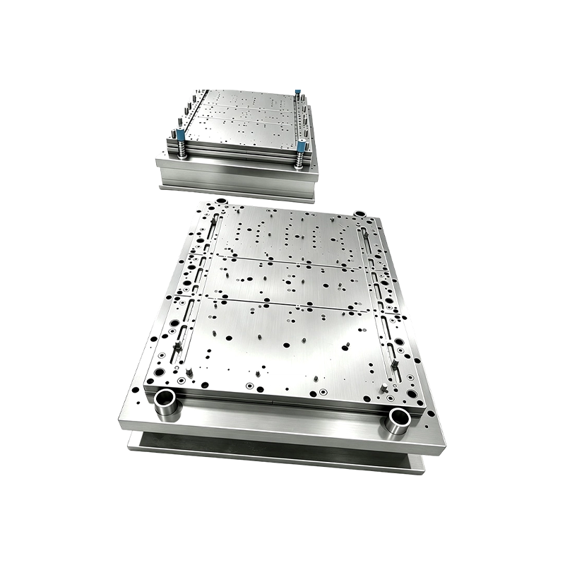
Progressive Stamping Die for Connector & Terminal Parts High Speed Progressive Stamping Die Precision Metal Hardware Stamping Tool mold for Connector Terminal Parts Automotive Components
Progressive Stamping Die for Connector & Termi...
-
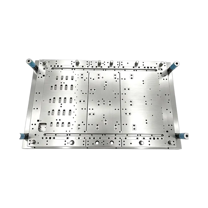
Multi-Station Progressive Stamping Die with Carbide Inserts Custom Multi Station Progressive Stamping Die Carbide Insert Metal Stamping Mold Tool for Equipment Appliances Device Hardware
High Speed Metal Stamping Tool for Precise Equipme...
-
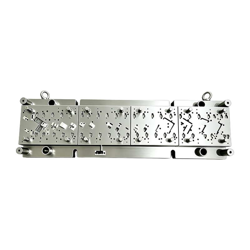
High Speed Progressive Stamping Die Sheet Metal Follow on Press Tool
Multi-operation Metal Stamping Tool for Continuous...
-
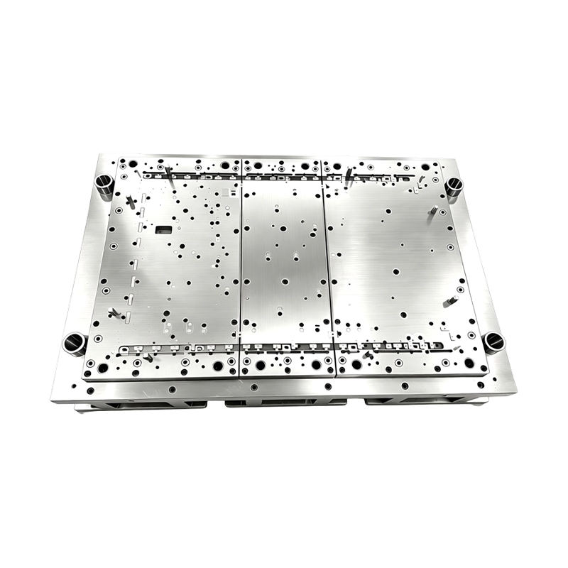
High Precision Stamping Die Multi Station Hardware Progressive Mold Tooling
Precision Metal Stamping Tool for Automotive &...
-
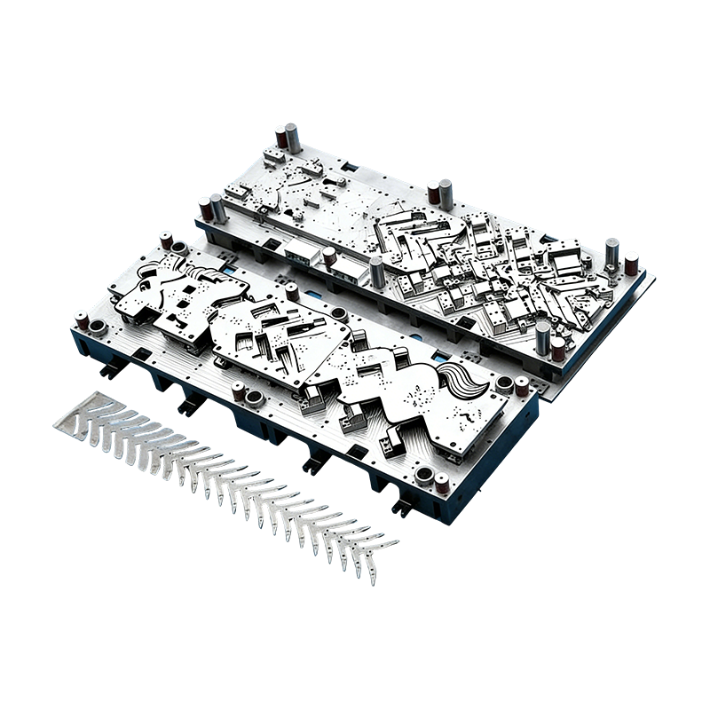
Progressive molds for automotive parts
This Continuous mold for automotive motor housing ...
- E-mail us: [email protected]
- Call us: +86-139 1308 8972

Zhou Mengjie – Technical Sales Specialist
Home / Author / Zhou Mengjie – Technical Sales Specialist / Long-Stroke Multi-Stage Progressive Dies for High-Precision Sheet Metal Forming
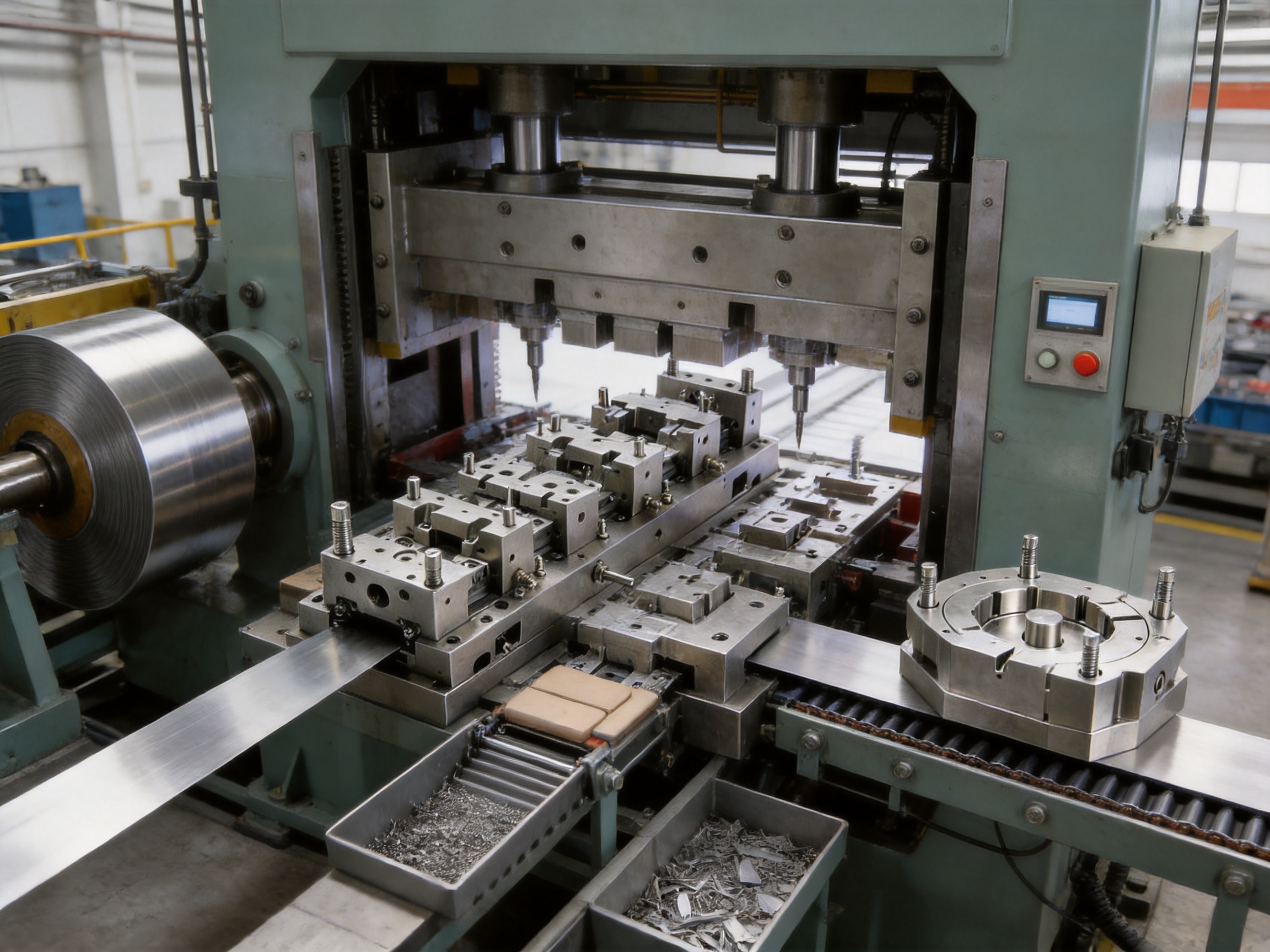
Long-Stroke Multi-Stage Progressive Dies for High-Precision Sheet Metal Forming
2026-09-24
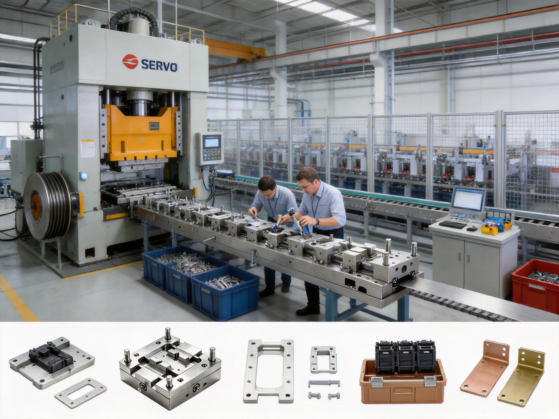
Modern sheet metal manufacturers are under constant pressure to produce more complex components at higher speed, with tighter tolerances, lower scrap rates, and fewer secondary operations. Automotive, electric vehicle, electrical, electronics, industrial automation, telecommunications, appliance, and aerospace suppliers increasingly require components that combine piercing, lancing, bending, embossing, coining, restriking, and blanking in one continuous production process. A conventional short progressive die may not provide enough space or forming flexibility for these demanding applications. A sequence of separate dies may solve the forming problem, but it increases handling, labor, tooling cost, floor-space requirements, and quality variation.
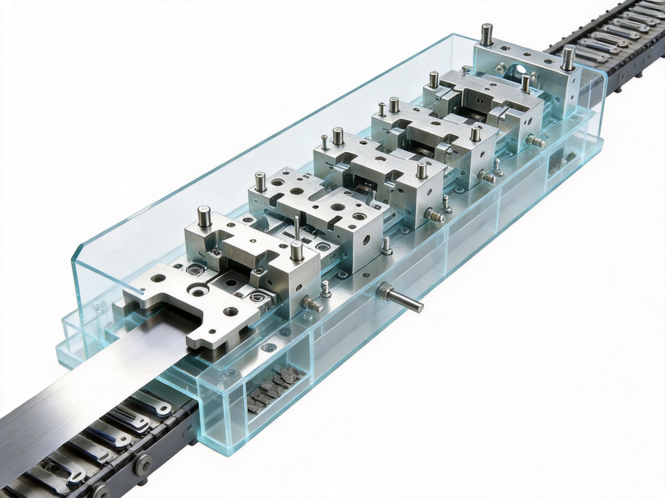
A long-stroke multi-stage progressive die provides a comprehensive solution. It is engineered with an extended die body and a larger number of forming stations arranged along the strip direction. As the coil advances through the die, each station performs a controlled operation. The strip is progressively transformed from flat sheet into a finished three-dimensional component, and the completed part is separated and discharged at the final station. This arrangement enables manufacturers to combine numerous operations into one automated, repeatable, and high-output production system.
The long-stroke progressive die described in this article is designed for complex sheet metal hardware and precision components requiring multiple sequential forming operations. It combines long-travel strip feeding, multi-point guidance, staged forming, springback compensation, modular inserts, integrated scrap management, and automated part ejection. The result is a durable tooling platform capable of supporting stable production for automotive brackets, battery-related components, connector housings, electrical clips, shielding parts, structural reinforcements, and many other formed sheet metal products.
Behind the tooling is an experienced manufacturing organization specializing in stamping dies, stamping parts, and stamping automation equipment. Its integrated capabilities include die design, precision machining, assembly, tryout, debugging, production support, and automation integration. This combination allows customers to obtain not only a die, but also a coordinated manufacturing solution adapted to their press, material, production volume, and quality requirements.
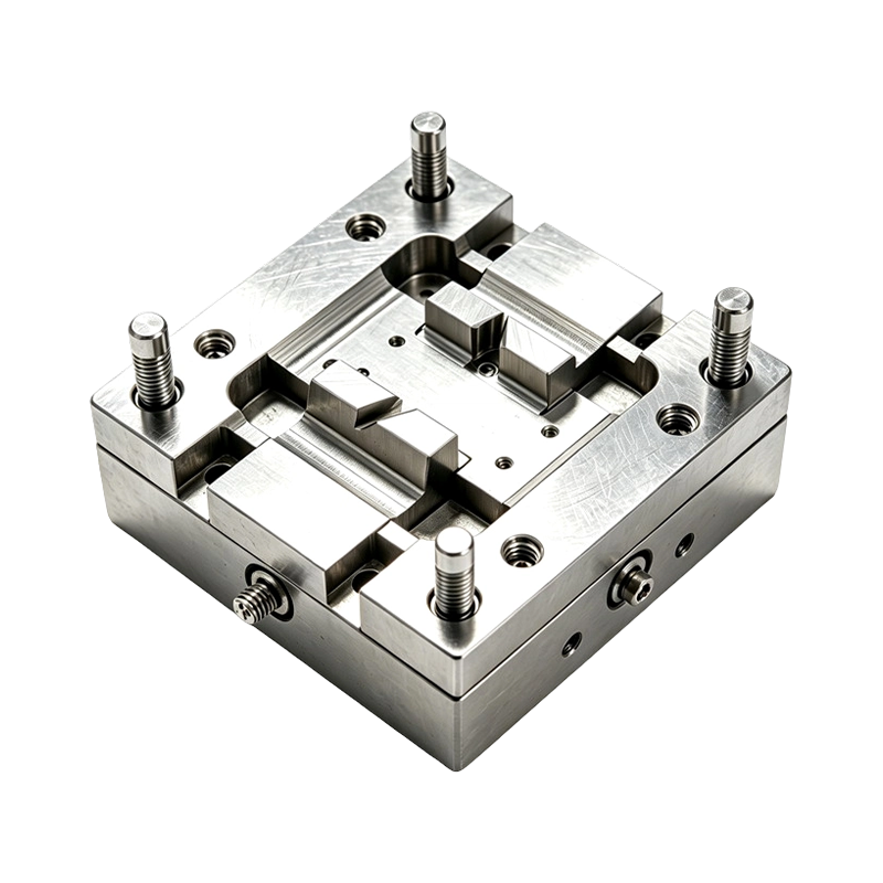
Long-Stroke Multi-Stage Progressive Die Automatic Strip Feed Progressive Die Long Travel Follow on Stamping Tool for Sheet Metal Hardware Press Moulding
Content
- 1 Understanding the Long-Stroke Multi-Stage Progressive Die
- 2 Why Long Multi-Stage Tooling Is Better for Complex Parts
- 3 Core Engineering Features
- 4 Applications Across Automotive and New Energy Manufacturing
- 5 Manufacturing Process and Technical Capability
- 6 Company Strengths and Integrated Supply Capability
- 7 Competitive Advantages Compared with Conventional Tooling
- 8 Material and Part Design Considerations
- 9 Maintenance, Service Life, and Production Support
- 10 Project Development Process
- 11 Questions and Answers
- 11.1 What is a long-stroke multi-stage progressive die?
- 11.2 How many stations can the die contain?
- 11.3 What operations can be included?
- 11.4 Can the die produce three-dimensional parts?
- 11.5 How does the tooling control springback?
- 11.6 Is the die suitable for high-strength steel?
- 11.7 How is strip alignment maintained over a long die body?
- 11.8 What is the benefit of modular inserts?
- 11.9 How is stamping scrap removed?
- 11.10 How are finished parts discharged?
- 11.11 What industries can use this tooling?
- 11.12 Can the supplier provide automation equipment as well as dies?
- 11.13 What press capacity is available for development and testing?
- 11.14 How does a customer begin a project?
- 12 Conclusion
- 13 References
- 14 Product: Long-Stroke Multi-Stage Progressive Die Automatic Strip Feed Progressive Die Long Travel Follow on Stamping Tool for Sheet Metal Hardware Press Moulding
Understanding the Long-Stroke Multi-Stage Progressive Die
A progressive die is a precision tool that performs several operations on a continuously fed metal strip. The strip moves through the die in fixed increments called pitches. At each pitch, one or more stations act on the material. The partly formed component remains connected to the carrier strip until the appropriate final station, where the finished part is blanked, cut off, or otherwise separated.
A standard progressive die may contain only a few stations for relatively simple components. A long-stroke multi-stage progressive die extends this concept by providing a significantly longer working area. The die can accommodate approximately eight to more than thirty forming stations, depending on the component geometry, material, press capacity, and required process sequence. The extended layout creates room for additional operations that cannot be safely or efficiently combined in a short die.
Typical operations may include pilot piercing, carrier preparation, lancing, hole piercing, notching, pre-bending, side bending, offset forming, embossing, drawing, restriking, coining, calibration, final trimming, and part separation. Each station is developed to perform a specific function with controlled force and carefully managed material flow. By dividing a complicated forming sequence into smaller steps, the tooling can produce complex 3D geometry while reducing the risk of cracking, distortion, excessive springback, or uncontrolled deformation.
The term “long-stroke” refers not only to the physical length of the die, but also to the extended progression of the strip through multiple forming stages. The system must maintain accurate registration across the entire travel distance. A small positioning error at an early station can become a significant dimensional problem at a later station. For this reason, long-stroke dies require advanced feeding, piloting, guiding, lifting, and pressure-control systems rather than simply a longer die plate.
From Flat Coil to Finished Three-Dimensional Component
The production cycle begins with a coil of sheet metal that is straightened and fed into the die. The first stations may prepare the carrier strip and create pilot holes. These pilot holes allow precision pins to register the strip at subsequent positions. Early piercing and lancing operations are then completed while the material is still relatively flat and easy to control.
Later stations progressively form the component. A large bend may be divided into a pre-bend, intermediate bend, final bend, and restrike operation. Embossed features can be formed before or after bending, depending on material flow and access. Critical surfaces may receive a coining operation to improve definition and dimensional stability. Final trimming and blanking occur only after the part has reached its intended shape.
The completed part is separated at the last stage and discharged through an air blow, mechanical kicker, conveyor, or another automated collection system. Scrap generated by piercing and trimming is routed through internal chutes or designated discharge channels. This prevents loose slugs from accumulating inside the die and reduces the risk of jamming or production interruption.
Why Long Multi-Stage Tooling Is Better for Complex Parts
Complex sheet metal components are often difficult to manufacture economically with single-operation tooling. Each additional die requires setup, alignment, material transfer, inspection, and handling. Even when the individual dies are simple, the total production process can become slow and inconsistent. A long-stroke progressive die consolidates many of these operations into a single automated line.
Fewer Secondary Operations
One of the most important advantages is the ability to complete several bends and formed features inside the progressive die. Parts that would otherwise require secondary presswork, manual bending, or separate restriking can be delivered as finished or nearly finished components. Reducing secondary operations lowers labor demand and avoids the dimensional variation that may occur when parts are moved from one process to another.
Fewer operations also reduce work-in-process inventory. Instead of storing partially completed parts between separate machines, manufacturers can feed the strip into one integrated system and collect finished components at the end. This improves production flow and makes scheduling easier, particularly for high-volume automotive and electrical applications.
Higher Repeatability
Progressive production provides consistent positioning and forming conditions. Once the die, feeder, press, and material parameters are properly set, every part follows essentially the same process path. The controlled sequence reduces differences caused by manual handling and makes it easier to maintain dimensional consistency over long production runs.
Repeatability is especially valuable for parts installed in assemblies with limited clearance. Connector housings, sensor brackets, battery supports, relay frames, and precision clips may require accurate hole locations, bend angles, offsets, and contact surfaces. The long-stroke die is designed to control these characteristics through pilot registration, staged forming, and final calibration.
Improved Material Flow
Large bends and complicated shapes can produce uneven material flow if they are completed in a single hit. Excessive deformation may cause splitting, wrinkling, distortion, or a loss of dimensional control. Dividing the forming process into multiple stages gives the material more opportunity to move gradually.
Pre-forming stations establish the shape without applying the entire final load at once. Intermediate forming stations then develop the geometry, while restrike and coining stations stabilize the final dimensions. This process is useful for high-strength steel, stainless steel, galvanized materials, copper alloys, aluminum, and other sheet metals that may have significant springback or limited formability.
Lower Handling and Labor Requirements
Manual transfer between separate dies introduces additional labor and creates opportunities for incorrect orientation, surface damage, and part mixing. Automatic strip feeding minimizes these risks. The material remains connected to the carrier strip while it moves through the die, allowing the press to perform the complete sequence without manual intervention.
Reduced handling is also beneficial for surface-sensitive components. Electrical shielding parts, decorative hardware, connector shells, and precision brackets can be damaged by repeated loading and unloading. An integrated progressive process helps protect surfaces and reduces the number of contact points outside the tooling.
Core Engineering Features
Extended Multi-Station Layout
The extended die body provides the space required for a carefully planned process sequence. Stations can be arranged to keep difficult operations separate, provide clearance for formed features, and control the order in which material is removed or displaced. A long layout is particularly useful when a component has multiple bend directions, deep offsets, narrow tabs, embossed ribs, side walls, or several piercing patterns.
Station planning begins with an analysis of the finished part and its flat pattern. Engineers evaluate material thickness, grain direction, bend radii, hole-to-edge distances, carrier design, scrap bridges, press tonnage, and required feed pitch. The operation sequence is then developed to balance forming loads and maintain strip stability.
Unlike a short die that may force several operations into one crowded station, the long-stroke configuration allows the process to be distributed. This can improve tool access, simplify insert design, provide better inspection visibility, and create more room for sensors, lifters, pilots, and scrap channels.
Sequential Bending and Springback Compensation
Springback occurs when elastic stresses in the material cause a formed feature to move away from its intended shape after the forming load is removed. The amount of springback depends on material grade, tensile strength, thickness, bend radius, grain direction, forming direction, and tooling condition. High-strength steels and stainless steels are often especially sensitive.
The die addresses springback through staged forming. A bend may begin with a gentle pre-forming operation, followed by one or more bending stations and a final restrike. The final station can apply controlled over-bending or coining to compensate for the expected elastic recovery. Because the process is distributed, each stage can be adjusted without changing the entire die architecture.
Springback compensation is not a substitute for proper material testing and process validation. However, it gives the tooling designer more opportunities to tune the final geometry. During tryout, the affected insert can be modified, polished, shimmed, or replaced to achieve the required angle and profile.
Long-Strip Stability and Anti-Warping Control
Long progressive dies require reliable support along the full strip path. As the strip passes through numerous forming stations, it can experience lifting, twisting, localized tension, and progressive warping. If these conditions are not controlled, the strip may fail to enter a station correctly, causing misfeeds, tool damage, or dimensional defects.
The tooling incorporates precision pilot pins at multiple intervals to maintain registration. Strip lifters support the material during die opening and closing, while pressure pads hold the strip in position during critical operations. Guide rails help control lateral movement and keep the carrier strip aligned with the feed direction.
These systems work together rather than operating as isolated components. The pilot pins establish accurate pitch location, the lifters prevent unwanted contact during return movement, the pressure pads stabilize the strip during forming, and the guide rails control side-to-side motion. This integrated approach is important when the strip has already undergone several bends and is no longer flat.
Heavy-Duty Die Base and Multi-Point Guidance
A long die must remain rigid and parallel under repeated press loads. Deflection can alter cutting clearance, bend depth, hole position, and forming pressure. Conventional guidance located only at the four corners may not provide sufficient control across an extended working area.
The long-stroke die uses a stress-relieved and precision-ground die base with multiple guide pillar sets distributed along the die length. Multi-point guidance helps maintain parallelism across the complete tool. It also reduces the risk of uneven wear and localized clearance changes.
This design helps prevent the “banana effect,” a condition in which a long die assembly bends or deflects along its length under load. The rigid structure is especially important for thick-gauge materials, high-strength sheet, high-tonnage operations, and dies expected to operate for millions of cycles.
Modular Forming Inserts
Each major bending or forming station can use an independently replaceable insert. This modular design offers practical advantages during development, maintenance, and production support. If a bend angle needs adjustment, the affected insert can be modified without rebuilding the entire die.
Modular inserts also simplify wear replacement. High-load cutting edges, coining surfaces, and forming radii may experience different wear rates. Separate inserts allow the maintenance team to replace only the worn element rather than removing a large integrated block.
When the customer changes material thickness, coating, strength grade, or part geometry, modular construction can shorten the modification process. It also reduces the cost and risk associated with design revisions. The die remains a stable platform while specific stations are adapted to the new requirement.
Integrated Scrap Management
Progressive dies generate scrap from piercing, lancing, trimming, and blanking. Loose slugs must be removed quickly and reliably. If scrap accumulates inside the die, it can become trapped between the upper and lower sections, damage inserts, mark the product, or stop the press.
Internal scrap chutes guide slugs toward designated discharge points. Their location and shape are planned during die design to avoid interference with structural components and to support easy cleaning. The system may be connected to a conveyor, scrap bin, vacuum device, or other factory collection arrangement.
Effective scrap management improves uptime and protects tooling. It also supports a cleaner working environment and makes preventive maintenance easier. Operators can inspect known discharge areas instead of searching through the entire die for accumulated material.
Automated Part Ejection
At the final station, the finished part is separated from the carrier. Depending on its shape, weight, and surface requirements, it may be ejected by an air blow, mechanical kicker, stripper system, or a combination of methods. The discharge method is selected to prevent part rotation, nesting, scratching, and obstruction at the die exit.
Automated ejection supports continuous production and eliminates the need for manual part retrieval at the press. Parts can be transferred directly to a conveyor, inspection device, counting system, packaging station, or downstream assembly process. This makes the die suitable for factories seeking a more connected and automated production line.
Applications Across Automotive and New Energy Manufacturing
The long-stroke multi-stage progressive die is particularly suitable for applications in which a relatively small or medium-sized sheet metal component contains several formed features. Automotive and electric vehicle manufacturing are important target markets because these industries require large volumes, stable quality, traceability, and efficient use of material.
Automotive Components
Potential automotive applications include seat brackets, door-panel clips, hinge components, sensor mounting brackets, brake line clips, electrical connector housings, reinforcement plates, and structural support parts. These components may include several bends, pierced holes, offsets, ribs, slots, or retaining features.
A progressive die allows such features to be produced in a controlled order. Piercing can be completed while the strip is flat, while bending and embossing can be distributed through later stations. Final restriking helps maintain the geometry required for assembly. For high-volume vehicle programs, the resulting reduction in handling can provide meaningful productivity and cost benefits.
Electric Vehicle and New Energy Components
Electric vehicles create demand for specialized sheet metal parts used in battery systems, electric motors, charging systems, thermal management assemblies, and high-voltage electrical equipment. Potential applications include battery module brackets, busbar support frames, cooling system clips, motor housing components, charging connector parts, and shielding elements.
Many of these parts require a combination of electrical clearance, mechanical stiffness, precise mounting holes, and controlled surface geometry. A long-stroke progressive die can form stiffening ribs, mounting features, tabs, and shielding shapes in a single strip-fed process. The process can also be adapted to copper, stainless steel, aluminum, and coated steel, subject to appropriate material validation.
Electrical and Electronic Hardware
Relay frames, terminal blocks, switch housings, connector shells, EMI shielding cans, PCB mounting clips, and other electrical hardware often require precise small features. Hole position and contact geometry may be critical to the operation of the finished assembly.
Progressive forming allows the piercing and forming sequence to be planned around the most sensitive features. Fine pilots and controlled strip support help maintain registration, while modular inserts make it possible to adjust individual contact or retention features during tryout.
Telecommunications and Data Center Equipment
Server chassis brackets, cable management clips, heat sink mounting parts, rack hardware, and shielding frames may require repeated bends and mounting features. These products are often produced in substantial quantities and may use stainless steel, galvanized steel, aluminum, or other conductive materials.
The long die format provides the station capacity needed to form complex brackets without transferring parts between several presses. Integrated discharge and scrap removal can support continuous manufacturing for data center hardware and telecommunications infrastructure.
Home Appliances and Industrial Automation
Appliance manufacturers may use such tooling for drum brackets, compressor mounting plates, hinge parts, control panel frames, and motor support structures. Industrial automation applications may include sensor brackets, actuator clips, conveyor components, relay sockets, and terminal strip housings.
These markets benefit from the die’s flexibility. A component can be designed around a progressive strip process, allowing high production quantities with controlled labor input. Modular inserts are also valuable when product families share a common base geometry but differ in a small number of forming details.
Aerospace-Related Sheet Metal Hardware
Lightweight bracket preforms, clip fasteners, and structural sheet metal components may also be suitable for this type of tooling when the material, tolerance, documentation, and quality requirements are properly defined. Aerospace-related programs demand careful process validation and traceability. Tooling can be developed for customers operating under quality systems compatible with aerospace manufacturing requirements, including AS9100-oriented environments.
Manufacturing Process and Technical Capability
The quality of a progressive die depends on more than the final assembly. It is determined by the complete manufacturing chain, including design analysis, material selection, machining accuracy, heat treatment, grinding, fitting, assembly, tryout, and production support. An experienced die manufacturer must coordinate each stage to ensure that the finished tool performs as intended.
Product and Process Review
Before machining begins, the part drawing and production requirements are reviewed. Important factors include material grade, thickness, coil width, feed direction, annual volume, press tonnage, stroke rate, required tolerances, surface requirements, and downstream assembly conditions.
Engineers evaluate whether the component is suitable for progressive forming and identify potential risks. These may include excessive draw depth, tight bend radii, difficult grain orientation, insufficient carrier strength, limited hole-to-edge distance, or excessive forming load. The process is then adjusted through station sequencing, reliefs, pre-forming, carrier design, and material utilization planning.
Die Design and Simulation-Oriented Planning
The die structure is designed around the complete strip layout rather than individual operations alone. Engineers determine the pitch, carrier width, station arrangement, pilot locations, lifter positions, scrap discharge routes, guide pillar locations, insert boundaries, and press interface.
For complex components, forming analysis and practical experience are used to estimate material flow and springback. The design may include pre-bend stages, restrike stations, relief areas, and replaceable inserts to increase the adjustment range during tryout. Clearances are selected according to material type, thickness, operation, and required edge quality.
Long dies require particular attention to structural deflection. The die base, plates, guide systems, and load-bearing sections must be designed to maintain alignment along the full length. Multi-point guidance is incorporated to support consistent performance across all stations.
Precision Machining
Precision machining is performed using advanced equipment such as CNC machining centers, imported wire-cut electrical discharge machines, and precision grinding machines. Wire cutting is useful for producing accurate profiles, cutting edges, and intricate insert shapes. CNC machining provides efficient and repeatable production of pockets, holes, steps, and complex three-dimensional surfaces.
Grinding is used to establish accurate thickness, flatness, parallelism, and surface finish. More than ten grinding machines of different sizes support the processing of components with varied dimensions. Proper grinding is essential for cutting clearance, insert fit, die shut height, and guide alignment.
Machining processes are coordinated with inspection requirements. Critical dimensions may be checked before an insert moves to the next operation. This helps identify errors early and prevents the accumulation of small inaccuracies across the die assembly.
Assembly, Fitting, and Tryout
After machining, die components are cleaned, inspected, and assembled. Fitting technicians verify insert seating, guide movement, stripper action, lifter timing, pilot engagement, and scrap passage. The die is then installed or tested in a suitable press for tryout.
Tryout is a practical engineering stage rather than a simple final inspection. Test material is run through the die, and samples are measured for hole position, bend angle, flatness, profile, burr condition, and surface quality. If a feature is outside the required range, the responsible station is analyzed and adjusted.
Because the die uses modular inserts, adjustments can often be made locally. A bend insert may be reworked to change an angle, a restrike surface may be refined, or a pilot and pressure-pad relationship may be corrected. This approach reduces modification time and helps preserve the accuracy of stations that are already performing correctly.
Press and Automation Integration
The manufacturer operates punch presses ranging from approximately 80 tons to 400 tons, providing experience with a broad range of stamping requirements. Press selection depends on the calculated forming and cutting loads, die dimensions, stroke requirements, feed pitch, material thickness, and desired production speed.
Stamping automation equipment can be integrated with the die to create a more complete solution. Systems may include coil handling, straightening, servo feeding, part conveyors, scrap removal, sensors, and collection equipment. Coordinating the die and automation at the design stage reduces interface problems during installation.
Automation also improves operational consistency. A controlled servo feeder can maintain accurate pitch, while sensors can detect misfeeds, strip-end conditions, or abnormal part discharge. The exact configuration depends on the customer’s press line and production objectives.
Company Strengths and Integrated Supply Capability
The manufacturer behind this product specializes in the design and production of stamping dies, stamped hardware parts, and stamping automation equipment. Its location in Suzhou provides access to an established manufacturing environment and a broad industrial supply network. The company has approximately fifteen years of experience in the mold industry and employs a technical team of around sixty people.
Its equipment base includes imported wire-cut machines, CNC machining centers, more than ten grinding machines of various sizes, and twenty-five punch presses with capacities ranging from 80 tons to 400 tons. This combination supports both precision toolmaking and practical production verification.
Experienced operators and debugging personnel provide support during assembly and tryout. Their role is important because a complex progressive die must be evaluated as a complete production system. The die, material, feeder, press, sensors, scrap handling, and part discharge must work together rather than being considered separate products.
The company serves customers in servo drives, compressors, new energy vehicles, electrical equipment, and related industrial fields. Its customer base includes industrial groups and technology manufacturers requiring dependable dies and stamped components. The company also established a related intelligent technology business to focus on stamping automation equipment, strengthening its ability to provide integrated solutions.
Design, Toolmaking, and Production Under One Capability Structure
A major advantage of an integrated supplier is communication. When die design, machining, tryout, stamping, and automation are handled by closely connected teams, design feedback can be transferred more quickly. Production issues can be traced to the appropriate station, and modifications can be coordinated without relying on multiple unrelated vendors.
This structure is particularly valuable for long dies. A tooling specialist may identify a forming issue, while a production engineer may recommend a feeder adjustment or a different discharge arrangement. A supplier capable of handling both die development and automation can evaluate the entire process and propose a coordinated solution.
Quality and Cost Control
Reliable tooling requires strict control of materials, machining, fitting, and inspection. The use of precision equipment and experienced technicians helps maintain consistency in critical areas such as insert profiles, guide alignment, die clearances, and plate flatness.
Cost control does not mean selecting the least expensive individual component. It means balancing initial investment with service life, maintenance requirements, production speed, scrap rate, and modification flexibility. Modular inserts, effective scrap discharge, and integrated automation can reduce total ownership cost over the life of the project.
The manufacturer emphasizes competitive pricing while maintaining technical capability. Its in-house resources allow many operations to be coordinated directly, reducing external processing dependencies and supporting more predictable project control.
Competitive Advantages Compared with Conventional Tooling
| Evaluation Area | Long-Stroke Multi-Stage Progressive Die | Short or Separate Single-Operation Dies |
|---|---|---|
| Complexity Handling | Supports many sequential bends, piercings, embosses, restrikes, and blanking operations. | May require several dies or secondary operations for the same component. |
| Production Flow | Continuous coil feeding with finished parts discharged automatically. | Often requires transfer, storage, and manual or robotic movement between operations. |
| Dimensional Consistency | Fixed pitch, pilot registration, staged forming, and integrated process control. | Variation can increase during repeated loading, unloading, and repositioning. |
| Springback Control | Pre-bending, final bending, restriking, and coining can be distributed across stations. | Large forming changes may be forced into one operation, limiting adjustment options. |
| Maintenance | Modular inserts allow local repair or replacement. | Integrated components may require more extensive disassembly or rework. |
| Scrap Management | Internal chutes and planned discharge points reduce slug accumulation. | Scrap handling may be less integrated and more dependent on operator intervention. |
| Labor Requirement | Lower part handling requirements and stronger compatibility with automation. | More labor may be needed for transfer, inspection, and secondary forming. |
| Long-Term Productivity | Suitable for high-volume production where reduced handling and stable cycle time are important. | May be practical for low-volume or simple parts but less efficient for complex high-volume components. |
The comparison does not mean that a long progressive die is the correct choice for every part. Simple components with low production volumes may be more economical in a single-operation die. However, when a part has multiple formed features and must be produced in large quantities, the long-stroke configuration offers significant advantages in automation, consistency, and total process efficiency.
Material and Part Design Considerations
Successful progressive forming begins with a part design suitable for strip production. Designers should consider bend radii, hole locations, carrier attachment points, material direction, reliefs, tabs, and the accessibility of each feature. A design that is acceptable for manual fabrication may require modification before it can be produced economically in a progressive die.
Material thickness and strength influence the required press capacity, cutting clearance, forming sequence, and springback compensation. High-strength steel may require additional pre-forming or restriking. Stainless steel may require attention to galling and surface finish. Copper and aluminum may require different clearances and handling methods. Coated materials may need special consideration to protect the surface and manage debris.
The flat pattern and carrier design must provide sufficient strip strength throughout the process. If too much material is removed early, the strip may lose stability before reaching the final stations. Therefore, some trimming or piercing operations may be delayed until the component has passed the most demanding forming stages.
Part tolerances should be allocated realistically. Tight tolerances on every feature may increase die complexity and maintenance requirements. The most important functional dimensions should be identified so the tooling can prioritize them through pilots, restrikes, coining, and controlled support.
Maintenance, Service Life, and Production Support
A long progressive die is a long-term production asset. Preventive maintenance is necessary to protect its accuracy and service life. Routine tasks may include cleaning scrap passages, checking pilot pins, inspecting cutting edges, lubricating guide components, verifying lifter movement, checking pressure pads, and monitoring insert wear.
Operators should pay attention to changes in press load, unusual noise, incomplete scrap discharge, inconsistent part dimensions, burr growth, and misfeed alarms. These signs may indicate worn cutting edges, damaged pilots, blocked chutes, loose fasteners, or changes in material condition.
Modular construction simplifies corrective action. If a single insert shows wear, it can be removed and replaced while the rest of the die remains intact. Spare inserts can be prepared in advance for high-wear stations, helping reduce downtime during scheduled maintenance.
Production support also includes documentation. A useful maintenance package may identify station functions, recommended clearances, replacement parts, inspection points, lubrication requirements, and adjustment procedures. Clear documentation helps the customer operate the die consistently and train maintenance personnel more effectively.
Project Development Process
Step One: Requirement Confirmation
The project begins with drawings, three-dimensional data, material information, production volume, press specifications, and quality requirements. The supplier reviews the component and confirms whether a long-stroke progressive process is appropriate.
Step Two: Process and Strip Layout
Engineers develop the strip layout and operation sequence. They determine the feed pitch, carrier design, pilot locations, forming order, scrap bridges, station count, and expected material utilization. Customer approval is obtained before detailed manufacturing proceeds.
Step Three: Detailed Die Design
The full die structure is designed, including plates, guide systems, pressure pads, lifters, inserts, sensors, scrap chutes, part discharge, and press interfaces. Special attention is given to load balance and long-body rigidity.
Step Four: Component Manufacturing
Die plates and inserts are machined by CNC, wire cutting, milling, drilling, and grinding. Critical surfaces are inspected during production. Components are prepared for assembly after dimensional and visual checks.
Step Five: Assembly and Tryout
The die is assembled and tested with the specified or equivalent material. Samples are evaluated for dimensional accuracy, forming quality, burrs, surface condition, feed stability, and discharge performance.
Step Six: Modification and Validation
Necessary adjustments are made to modular inserts, pilots, pressure pads, lifters, or other components. The die is tested again until the process reaches the agreed requirements. Production capability and repeatability are reviewed before delivery.
Step Seven: Installation and Ongoing Support
The customer receives guidance for die installation, feeder setup, press adjustment, lubrication, maintenance, and troubleshooting. Where required, automation equipment and related production systems are integrated to support a turnkey stamping solution.
Questions and Answers
What is a long-stroke multi-stage progressive die?
It is a progressive stamping tool with an extended die body and numerous forming stations arranged along the strip direction. The strip advances through the stations in fixed pitches, and each station performs a specific operation until the completed part is separated and discharged.
How many stations can the die contain?
The configuration can accommodate approximately eight to more than thirty stations, depending on the part geometry, material, press capacity, feed pitch, and number of required operations. The final station count is determined during process and strip-layout development.
What operations can be included?
Typical operations include piercing, lancing, notching, pre-bending, final bending, embossing, coining, restriking, trimming, and blanking. The sequence is customized to the component and the required dimensional results.
Can the die produce three-dimensional parts?
Yes. The die is intended for components with multiple bends, offsets, embossed features, side walls, tabs, and other 3D geometry. These features are formed gradually through several stations rather than in one severe operation.
How does the tooling control springback?
Springback is controlled through staged forming, pre-bending, final bending, restriking, and, where appropriate, coining or controlled over-bending. The exact compensation depends on material properties and is confirmed during tryout.
Is the die suitable for high-strength steel?
It can be suitable for high-strength steel when the material grade, thickness, forming limits, press capacity, radii, and process sequence are properly evaluated. High-strength materials may require additional forming stages, stronger construction, and more extensive tryout.
How is strip alignment maintained over a long die body?
Strip alignment is maintained through multiple pilot pins, guide rails, pressure pads, and strip lifters. These components work together to prevent lifting, twisting, lateral movement, and progressive warping during long-travel feeding.
What is the benefit of modular inserts?
Modular inserts allow individual stations to be adjusted, repaired, or replaced without dismantling the entire die. This reduces maintenance time and makes it easier to compensate for material variation or accommodate future design changes.
How is stamping scrap removed?
Scrap slugs and trimming waste are routed through internal chutes to designated discharge points. The arrangement is designed to prevent buildup inside the die and support continuous production.
How are finished parts discharged?
Finished parts can be ejected by air blow, mechanical kicker, stripper action, conveyor transfer, or a combination of these methods. The selected system depends on part geometry, surface requirements, orientation, and production-line layout.
What industries can use this tooling?
Applications include automotive, electric vehicles, new energy systems, electrical and electronics, telecommunications, data centers, home appliances, industrial automation, and selected aerospace-related sheet metal programs.
Can the supplier provide automation equipment as well as dies?
Yes. The company has a related intelligent technology capability focused on stamping automation equipment. It can coordinate dies, feeders, conveyors, scrap removal, and other production equipment to support an integrated or turnkey solution.
What press capacity is available for development and testing?
The manufacturing facility includes punch presses ranging from approximately 80 tons to 400 tons. The appropriate press is selected according to the die size, material, forming load, cutting load, stroke, and production requirements.
How does a customer begin a project?
The customer can provide part drawings or three-dimensional data, material grade and thickness, target production volume, press information, quality requirements, and automation expectations. These details allow engineers to evaluate the process and prepare a suitable die concept.
Conclusion
The long-stroke multi-stage progressive die is an advanced solution for sheet metal components that cannot be efficiently produced through simple blanking or a small number of forming operations. Its extended station layout allows piercing, bending, embossing, restriking, coining, trimming, and blanking to be combined in one continuous strip-fed process.
Its main competitive advantages include reduced secondary operations, improved dimensional consistency, lower handling requirements, staged springback compensation, reliable long-strip support, multi-point die guidance, modular maintenance, integrated scrap management, and automated part ejection. These features make it especially valuable for high-volume components used in automotive, electric vehicle, electrical, industrial, and new energy applications.
The manufacturer strengthens this product through integrated die design, precision machining, grinding, assembly, tryout, stamping, and automation capabilities. Its technical staff, CNC and wire-cut equipment, grinding resources, punch press range, and experienced debugging personnel support the development of practical and reliable production tools.
For customers seeking a complete stamping solution rather than an isolated die, the combination of tooling and automation expertise provides an important advantage. By evaluating the component, material, press, strip layout, forming sequence, scrap path, and finished-part discharge as one system, the supplier can help create a production process that is more stable, more efficient, and easier to maintain over the long term.
References
1. ASM International, ASM Handbook, Volume 14B: Metalworking—Sheet Forming.
2. Society of Manufacturing Engineers, Tool and Manufacturing Engineers Handbook: Forming.
3. American Society of Mechanical Engineers, Standard Practices for Press Tool Design and Manufacturing.
4. International Organization for Standardization, ISO 9001: Quality Management Systems—Requirements.
5. International Organization for Standardization, ISO 12100: Safety of Machinery—General Principles for Design.
6. Automotive Industry Action Group, Production Part Approval Process Reference Manual.
7. Automotive Industry Action Group, Advanced Product Quality Planning and Control Plan Reference Manual.
8. Aerospace quality management guidance related to AS9100-compatible production and process control.
9. General engineering practice for progressive die design, sheet metal forming, press automation, springback compensation, and precision tooling maintenance.
Product: Long-Stroke Multi-Stage Progressive Die Automatic Strip Feed Progressive Die Long Travel Follow on Stamping Tool for Sheet Metal Hardware Press Moulding
Previous Post
Car Seat Stamping Parts: Precision Metal Components for Safe, Stable, and Efficient Automotive Seat Manufacturing
Next Post
High-Precision Car Seat Stamping Parts for Reliable Automotive Seat Structures
Our Products.
Start Your Business with an OEM Manufacturer Right Here!

Provide global customers with complete turn-key solutions
through
innovation!
QUICK LINKS
CONTACT INFO.
-
 +86-139 1308 8972
-

-
 No. 118 Yexin Road, Wujiang Economic Development Zone, Suzhou, China
Copyright © Suzhou Shuangqisi Mold Equipment Co., Ltd. All Rights Reserved. Custom Stamping Die Metal Stamping Die Manufacturers
